Quantcast
Channel: GameDev.net
Viewing all 17825 articles
Browse latest View live

Physically Based Shading For Artists

$
0
0
Hello Ladies And Gentlemen!

I'm happy to present you here a quick yet thorough introduction into the world of next gen physically based shading made specifically for artists.

My only hope in doing this is that more artists get to worry less about technical issues. Believe me, core artistic values will still be key in the coming generation of computer graphics, so just listen to this and forget about it until you get an actual tool to test all your new knowledge on. Concentrate on colors, lighting and composition instead and when the time comes you'll harness all the next gen awesomeness to do something truly outstanding!

Regards,
Andrew


P.S.As a bonus I'm giving away a next gen asset with some hints on how to author the maps:


Why Leadwerks? (An Opinionated Reflection on Two Game Engines)

$
0
0

Rain in the Valley


It's been a rainy week and there is a flu epidemic in Sacramento. Hacker Lab, the city's premier incubator and coworking space, hosted the 4th semiannual Cereal Hack, a 30-hour competition to support innovation in the City of Trees. On offer: plenty of fruit loops; a brain-controlled competitive beer tap; Thousands of dollars in prizes; a chance for some personal reflection?

Why Leadwerks? (An Opinionated Reflection on Two Game Engines)


Saturday: Sitting in the common area of Hacker Lab and surrounded by some extraordinarily talented indie developers and entrepreneurs, I was ready to throw in the towel. Hours of trying and failing to translate a hasty white-board design into a viable Unity game (combined with a persistent cold) had made this weekend hackathon unproductive and frustrating. Rather than continue to waste my time, I packed up and went home to bed. This was not my weekend.

Sunday: Sitting in my dining room in the twilight between waking up and my wife waking up (the witching hours of code) I pulled together a Lua scripting interface, a unit testing framework, and some performance profiling reports for Wings. In the planning meeting last week, there was a lot of concern about whether we would have enough time to tackle our entire vision. The Wings project is being constructed as the culminating requirement for the team's undergraduate degrees. We had two semesters, and we've used one of them. Making significant progress on three major requirements is no small accomplishment.

This contrast of experience emphasized for me why I enjoy working with Leadwerks, and why I will probably steer clear of Unity in the future.

This was not my first attempt at using Unity. I'm a serial project prototyper. I like to make demos and prototypes, and then move on to new things, so I've used a lot of platforms a time or two. I don't dislike the software. The user experience is fantastic, the tutorials and documentation are great, and the engine itself is impressive.

My issue is not with any of those, but with the way that Unity imposes itself on the game developer. The structure of a Unity game, of game objects and components and scripts, is such that it is incredibly easy to use the tools that are provided, and not easy at all to recognize the underlying software. The process feels almost magically simple, but also deceptively unlike anything that a traditional programmer is used to. Unity is the Ruby-on-Rails of game development: if you're doing it The Right Way, you won't need anything else. But game development, especially for indies, has to be about innovation over convention. Creating novel experiences implies crossing boundaries that nobody thought needed to be crossed and I would argue this is just as true at the technology level as it is at the interaction level.

My hackathon concept was a backburner idea I've had for a terrestrial rover simulator. It isn't very complex, but it requires modifying the normal temporal and physical models and that was enough to torpedo my prototype. I'm fairly certain a Unity expert could have made it work, but that isn't my perspective.

Working with Leadwerks is an entirely different beast. Leadwerks comes in C++ and Lua flavors but I am using the C++ edition and my experiences reflect that. It features a slick OpenGL 4 renderer and it just became the first 3D engine on Steam in December. It has come a long way in the past few years and has a long way to go to catch up with the big guys.

But what is especially interesting to me is that Leadwerks at its core still has the feel of an API. When I create a Leadwerks project, it has a main method with a game loop. Omitting some of the more detail oriented code, this is essentially what you get:

int main(int argc, const char* argv[])
{
    ...
    App* app;
    if (app->Start())
    {
        while (app->Loop()) {}
        ...
      	return 0;
    }
    ...
    return 1;
}    

The autogenerated App class doesn't inherit from anything or apply any partial class scheme to include a bunch of code. It has a Start method and a Loop method. Start creates a World and loads a Map, Loop updates the Time and the World and the player input.

Building a game in Leadwerks is like rendering a scene in OGRE or simulating a world in Bullet, except with easy to use tools for good measure. The end product is a body of code that any programmer could understand without knowledge of the engine itself. It can be as organized or as free-form as you like. For me, this means that development is often hard, but it's hard in exactly the ways that I am really good at overcoming. I have been wrestling with complex objects and algorithms for over a decade. I am intimately familiar with Visual Studio's quirks. I am adept at googling up arcane solutions to uncommon programming problems. Leadwerks lets me exercise all of these abilities and enjoy the rewards.

Leadwerks also allows me to manipulate things that were not intended to be manipulated. At times, this level of freedom can lead to intensely painful debugging, but it can also allow for precisely the kind of innovative solutions that indies depend on. It also provides a foundation for (I think) some pretty cool add-on functionality:


Attached Image: TwoGoblins.jpg


In this screen capture, Wings is controlling the two goblins and the player's barbarian. The attacking goblin is defined in C++ and attached to the model during the map load, while the recently expired goblin is initialized using the in-progress Lua bindings for Wings. Providing these sort of deep hooks into the engine while maintaining a reasonable level of abstraction (Wings has a core library of engine-agnostic functionality) would be much more difficult in a more constricting environment.

Don't get me wrong, I am not a programming paradigm Luddite bemoaning the current era of software development. To the contrary, I am a professional software developer. I appreciate the value of programming constraints, and the utility of applying best practices. I vastly prefer modern software engineering to old-school get-it-done hacking. But when the hammer is so bulky that I can't see the board, driving the nail is a frustrating experience.

Unity is a slick, refined factory when what I really need, given my resources, are some very sharp hand tools. I don't love everything about Leadwerks. In places the engine itself is still rough and the decision to avoid removing deprecated functionality (in spite of the fact that new versions almost always include breaking changes) causes some unnecessary confusion. But as a whole, I find I am much more confident and productive using Leadwerks and that outweighs a lot of minor quibbles.

Disclaimer


I am not an unbiased reviewer, and this really isn't intended to be a review of either Leadwerks or Unity, but rather an explanation of why I find some of the most popular game engines to be harmful to indie development. Josh Klint, CEO of Leadwerks, is the project sponsor (requirements oversight, not financial) for Wings but has provided no input to this article.

Article Update Log


10 Feb 2014: Initial release

GameDev.net Soapbox logo design by Mark "Prinz Eugn" Simpson

How To Setup a BlackBerry 10 Development Environment to Build Cascades Apps

$
0
0
This is a step-by-step instructional guide on how to setup a BlackBerry 10 (BB10) development environment. This article includes instructions for downloading all the Cascades tools, installing them, and setting them up. You will learn how to get the BB10 simulator up and running and then how to connect it up to the momentics IDE to run and test code. You'll also learn how to connect to a physical BB10 device so that you can run code on a real device.

A Little Background Information


Prior to BB10, app development for BlackBerry was done using Java or HTML5. You'll find references to the older development environment as "Developing for BlackBerry OS".

BlackBerry purchased QNX in 2010 and adopted their tools for use to build the BB10 environment. Before BB10 was ready the BlackBerry PlayBook tablet was released running the new QNX OS. To build applications for PlayBook you were given the following options to choose from:
  • Native (C/C++, OpenGL)
  • HTML5
  • Adobe AIR
  • Android Runtime
About a year after the PlayBook was introduced the first BB10 device (Z10) was released. When developing apps for BB10, you have many different options to choose from:
  • Native Cascades (C/C++, Cascades QML)
  • Native Core (C/C++, OpenGL)
  • HTML5
  • Adobe AIR
  • Android Runtime
  • Appcelerator (BlackBerry Platform Partner)
  • Cordova HTML5 framework (BlackBerry Platform Partner)
  • dojo HTML5 framework (BlackBerry Platform Partner)
  • jQuery Mobile HTML5 UI framework (BlackBerry Platform Partner)
  • Marmalade cross platform development environment (BlackBerry Platform Partner)
  • Qt (BlackBerry Platform Partner)
  • Sencha Touch HTML5 framework (BlackBerry Platform Partner)
  • Unity Game Engine (BlackBerry Platform Partner)

The Native Cascades Development Environment


When building apps for BB10, the preferred route is to write your code using Cascades in the Momentics IDE. Cascades is a framework developed by The Astonishing Tribe (TAT) which is an extension of Qt. In this article I describe how to setup a Windows PC for use to make BB10 applications using Cascades.

Get the Momentics IDE


To start you will need to download the Momentics IDE. You can download the current version of the software from the BlackBerry developer site located here.

Choose your platform from the website, download the installer and run it. At the time that I am writing this article, the current version of the Momentics IDE is version 2.0. I'm using Windows 7 to set everything up so I see the following when the installation program starts.


Attached Image: 00-momenticsInstall.png


Click Next through a series of dialogs, accept the license agreement and choose an installation directory (C:/bbndk is a good default). After doing all of that, find the new icon on your desktop and launch the Momentics IDE for BlackBerry.

First Run of the Momentics IDE


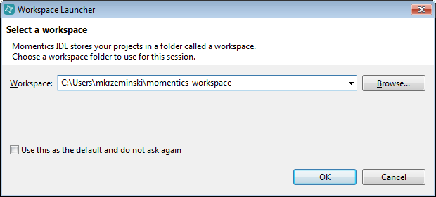
When the Momentics IDE starts up for the first time you will see the following dialog appear.


Attached Image: 01-workspace.png


This dialog is asking you for the location where you want to place all the source code that you will be using to make BlackBerry applications. Either accept the default path that it gives you or choose another location. I also recommend enabling the checkbox that reads "Use this as the default and do not ask again" to prevent this dialog from popping up in the future when you start the IDE.

After you click the OK button, the IDE will start up and notice that you are missing some SDK files. At this point you should see the following dialog appear.


Attached Image: 02-initDialog.png


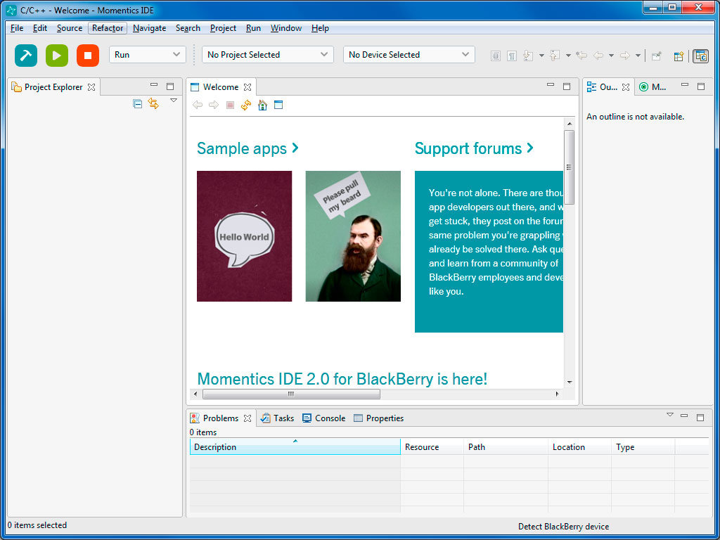
We will come back to setting up the SDK files in a minute, so right now just click the Cancel button in the bottom right corner. You should now see the main screen in the IDE that looks something like this:


Attached Image: 03-initScreen.jpg


The IDE is now installed so next up we will setup a BB10 simulator. For now just close the IDE.

BlackBerry 10 Simulator


You can find the latest version of the BB10 simulator to download here.

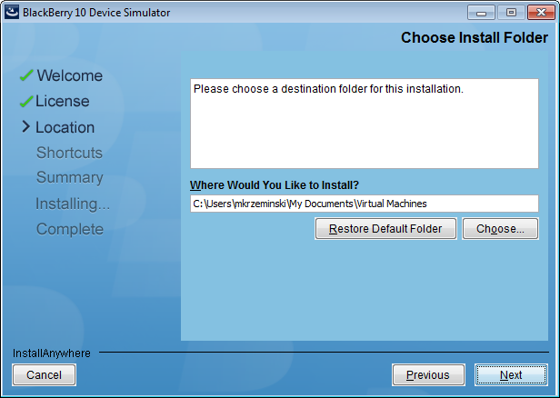
Download the installer and then run it to install the simulator on your computer. Click Next through the welcome dialog and accept the license agreement. You will then be asked where you want to install the simulator's virtual machine (VM) files.


Attached Image: 04-vmDir.png


Remember where you install the VM because you'll need this location in some following steps below. The simulator runs in a virtual environment which tries to simulate the behaviour of the BB10 hardware on your PC. For additional information about the BB10 simulator have a look here.

To run a VM, make sure that your PC has the minimum system requirements listed here.

You will need some additional software installed on your PC to run the BB10 simulator so I will be installing the VMware Player on my Windows PC. You can click the link found on the system requirements webpage or head down to https://www.vmware.com/tryvmware/?p=player&lp=1 to get a copy of the free VM Player.

After you install the VMware player, you should see a new icon on your desktop like this:


Attached Image: 05-vmWare0.jpg


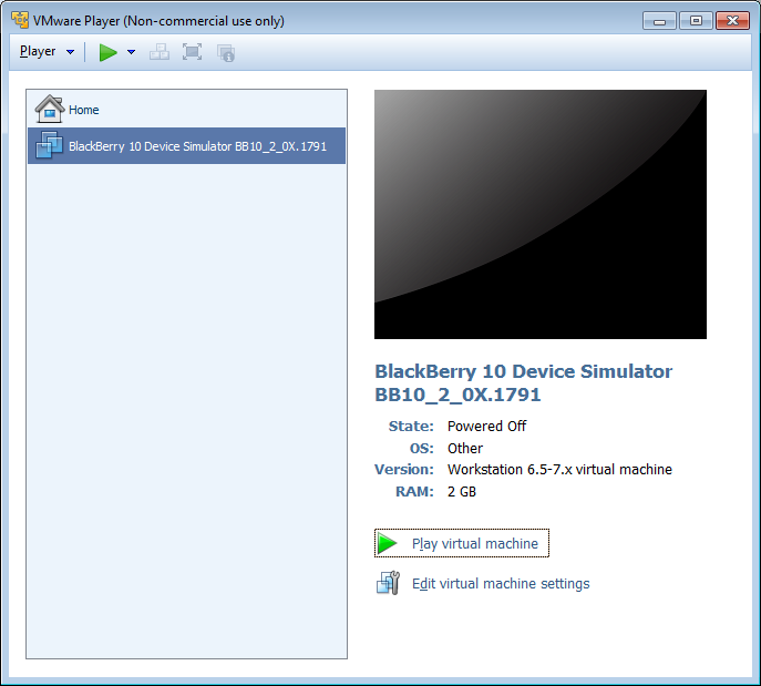
Launch the VMware player to see initial screen where you can select a VM to run.


Attached Image: 06-vmWare1.png


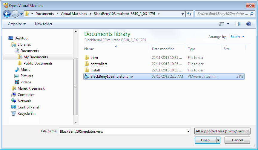
Select the "Open a Virtual Machine" option shown in the image above and then navigate to the directory where you installed the BB10 simulator.


Attached Image: 07-vmWare2.png


Select the BlackBerry10Simulator.vmx file and click Open.


Attached Image: 08-vmWare3.png


You should now see the BB10 Simulator listed in the VMware Player as shown in the above image. Select the BB10 Simulator in the list on the left and then you can edit the VM settings by clicking on the "Edit virtual machine settings" option found in the bottom right. I will leave my BB10 simulator with the default settings so just click the "Play virtual machine" option to start the simulator.

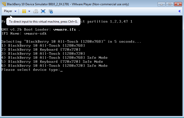
The BB10 simulator will start to load and a screen will appear asking you which BB10 device you would like to simulate.


Attached Image: 09-vmWare4.png


I'm running the BB10_2_0X.1791 version of the simulator so I see six options. Option 1 lets me simulate a Z10 device, Option 2 simulates a Q10/Q5 device, Option 3 simulates a Z30 device. The last three options are the same as the above three but just with Safe Mode enabled.

If you don't choose an option, one will be selected for you automatically after a few seconds.

Select an option or wait for the default to be selected and after a few minutes, the simulator will finish loading and you will see the BB10 interface on the screen. The BB10 OS is heavily based around swipe gestures to navigate between different screens. To produce a swipe in the simulator press the left mouse button down on your mouse, move the mouse in the direction you want to swipe, and then release the left mouse button.


Attached Image: 10-vmWare5.jpg


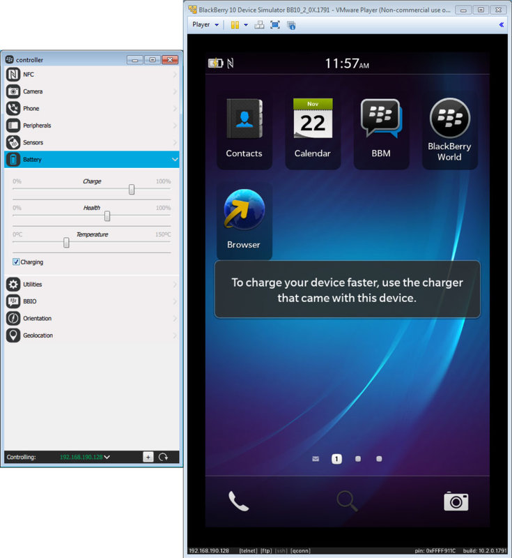
Now let us take a quick look at how you can control different options in the simulator. If your mouse focus is inside the simulator press Ctrl+Alt to free it and have it leave the VmPlayer. Click on your Windows Start button and navigate to Programs > BlackBerry 10 Simulator directory and launch the Controller program.

The controller is an external program used to control different options in the BB10 simulator. If the BB10 simulator is running when the controller is started it should automatically find and connect to it. You will know when this happens because in the bottom left hand corner of the controller, you will see that it says which IP address the controller is controlling.

Using the controller you can simulate NFC transactions, simulate phone calls, sensors etc. For example open the Battery category in the controller. Have a look in the top left hand corner of the BB10 simulator to see what the current battery icon looks like.

Now in the controller click the Charging checkbox to simulate the effect of the BB10 device being plugged in to charge the battery. You should now see in the BB10 simulator that the battery icon has a lightning bolt through it as shown in the image below. You can also use the sliders here to control how much charge the "simulated" battery has in your BB10 Simulator.


Attached Image: 11-vmWare6.jpg


Play around with the other controller options to see what things you can manipulate in the simulator.

BB10 Simulator Setup in the IDE


Now that we have the BB10 simulator installed and running in the background, let's get the IDE hooked up to it.

Launch the Momentics IDE again and when it starts up, close the initial start up dialog if it appears. Click on the drop down menu that says "No Device Selected" to open it, and select "Manage Devices..."


Attached Image: 12-setup0.png


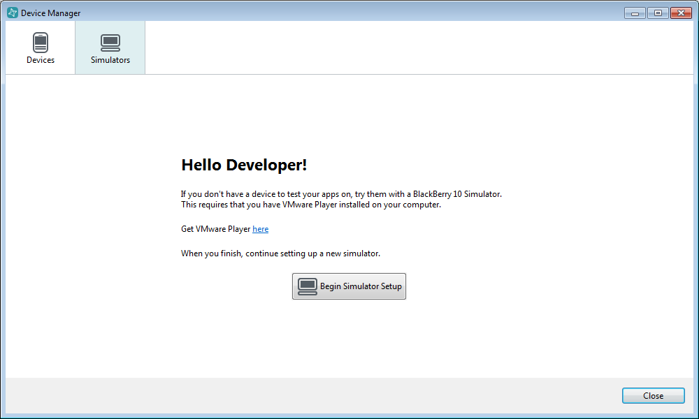
In the new dialog that appears, select the simulators tab at the top of the dialog, and then click on the "Begin Simulator Setup" button.


Attached Image: 13-setup1.png


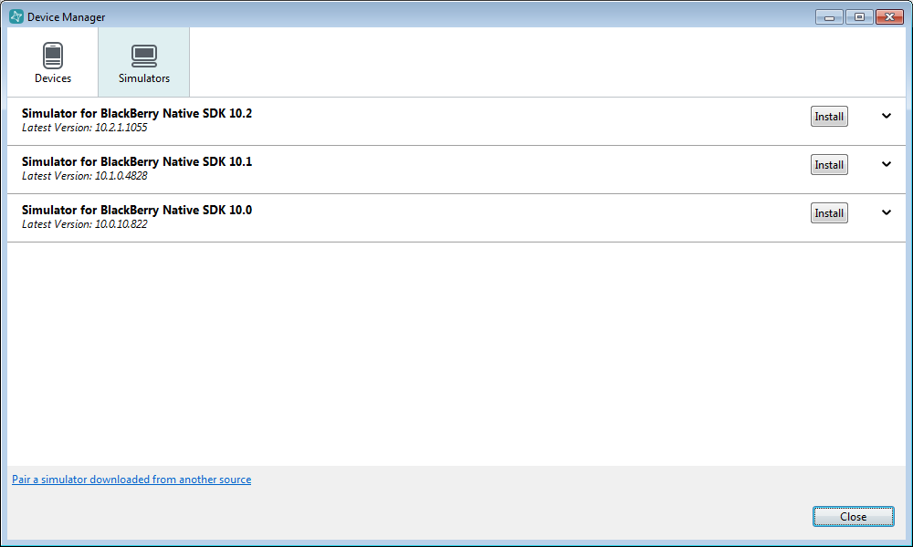
You will be presented with a list of BB10 Simulators that you can install. Since we already downloaded and installed a simulator we don't have to do it from these options. Instead, notice that in the bottom left hand corner of the dialog there is a link to "Pair a simulator downloaded from another source".


Attached Image: 14-setup2.png


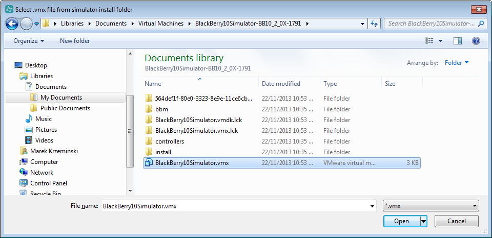
When you click the link to pair a simulator with the IDE, a dialog will open asking you to select the vmx file that you previously installed. Navigate to the location where you installed the BB10 simulator VM earlier, and select BlackBerry10Simulator.vmx.


Attached Image: 15-setup3.png


The Device Manager dialog will update and ask you for the IP address of the BB10 simulator that you want to connect to. You can either manually enter the IP address (which you can find in the bottom left hand corner of the running VM) or just click the "Auto-Detect" button in the IDE to have it find the simulator for you. Make sure your simulator is up and running. Once you have an IP address entered, click the Pair button.


Attached Image: 16-setup4.png


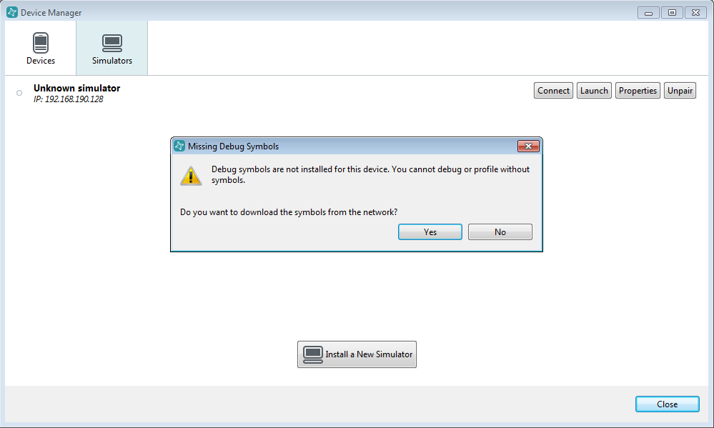
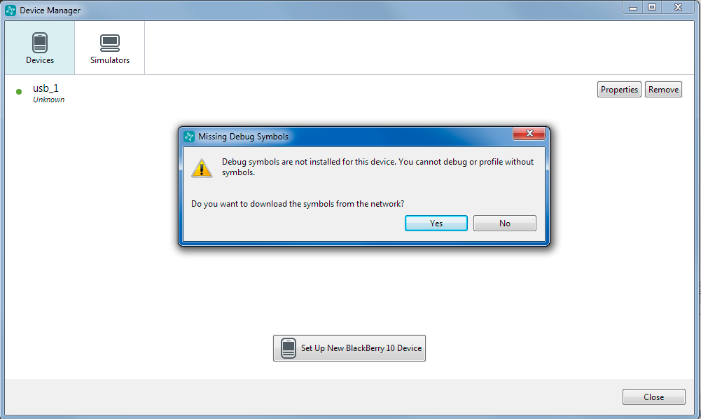
The IDE will connect to the simulator and realize that you are missing some debug symbols which are need when you try to debug apps. Click "Yes" in the dialog to download the symbols from the internet.


Attached Image: 17-setup5.png


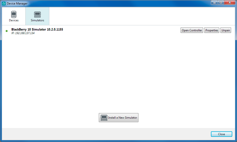
Once the debug symbols are downloaded you should see your simulator listed and the version of the BB10 OS that is currently supported by the simulator listed here. If you want to change your simulator or install a new simulator you can do that from this Device Manager dialog.

Notice that you can launch the BB10 Simulator controller directly from this dialog by clicking the "Open Controller" button rather than having to find the Controller program in your start menu.


Attached Image: 18-setup6.png


Updating the BB10 API Level


Anytime that BlackBerry releases a new version of their OS, a new Application Programming Interface (API) will come with it. That means if you want to take advantage of the new features, you'll need to download the new API. This also means that you'll need to download a new simulator that supports the new features.

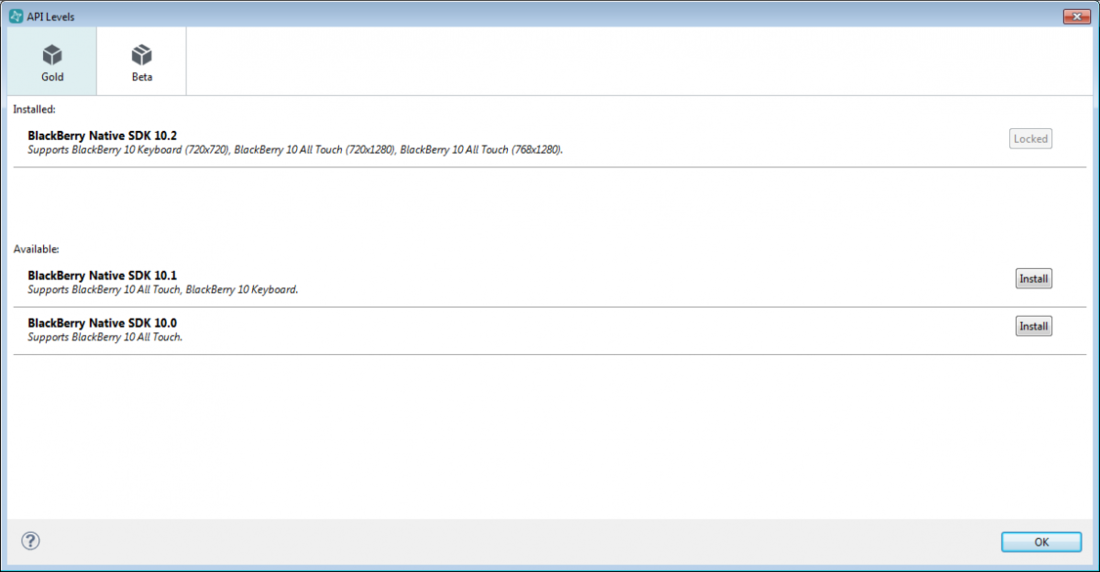
To install a BB10 API level in the IDE, click on the Help menu, and choose Update API Levels...


Attached Image: 19-api.png


A dialog will appear showing which API you currently have installed (if any) and which ones you can choose to download and install. Also notice that you can choose "Beta" versions of new API using the tab at the top of the dialog. Beta API give you a glimpse of what is coming up in the next version, however be careful with Beta API, there may be bugs in them, or the API may change before they are fully released.

Choose the latest API level (and the one that is supported by your simulator) from this dialog by clicking the appropriate install button on the right.


Attached Image: 20-sample10.png


When the API is done downloading and installing you will see it listed at the top of the dialog as shown below.


Attached Image: 21-sample11.png


Anytime you install a new API level, make sure you close the IDE and restart it.

Installing a BB10 Sample App


There are lots of BB10 sample apps that you can download and try, to learn how to program and make BB10 applications. I'll step you through the process of downloading and installing a sample app next.

When the momentics IDE starts up, you will see the Welcome tab (unless you turned it off) that contains links to sample apps. This isn't the only way to get sample apps!


Attached Image: 22-sample0.png


Head down to the BlackBerry developer site found here: http://developer.blackberry.com/native/sampleapps/

On this webpage you will see a listing of many different Cascades apps that you can download and try. Go and download the app called "Pull My Beard" which is found in the UI section.

Click on the icon on the webpage to open a description of the app, and then select the Download source code button.


Attached Image: 23-sampleApp.jpg


Once the zip file is downloaded to your computer, go back to the IDE and right click inside the Project Explorer tab on the left side. Make sure you right click in the white space and not on the BlackBerry10Simulator target which is also listed here.

Now choose Import... from the menu.


Attached Image: 24-import.png


The import dialog will appear on the screen. Open the General folder, and choose "Existing Project into Workspace". Then click Next.


Attached Image: 25-sample6.png


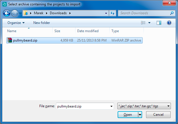
In the next dialog select the "Select archive file:" radio button option and click the Browse... button. Navigate to your download folder, and choose the zip file that you just downloaded from the BlackBerry developer website. Click the "Open" button.


Attached Image: 26-fromArchive.png


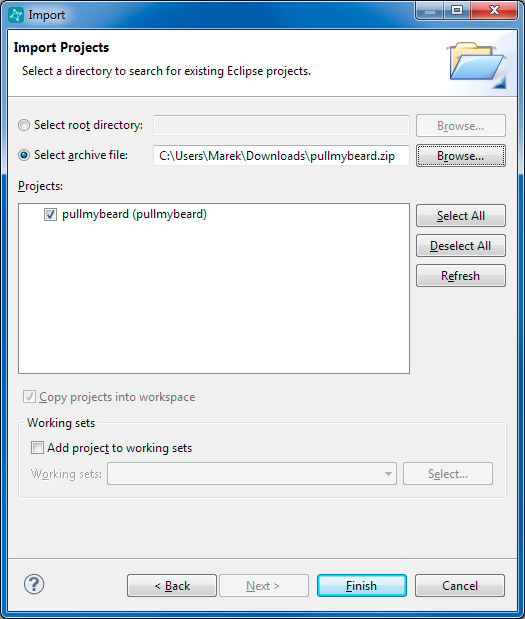
The IDE should recognize that the Pull My Beard application is inside the zip file so it will list it in the projects section. Click the Finish button to copy the Pull My Beard app out of the zip file and into your workspace.


Attached Image: 27-finish.png


Take a look on your hard drive in the workspace folder (default location is C:\Users\yourName\momentics-workspace) to see that you should now have a new folder named pullmybeard that has all the source files for the app.

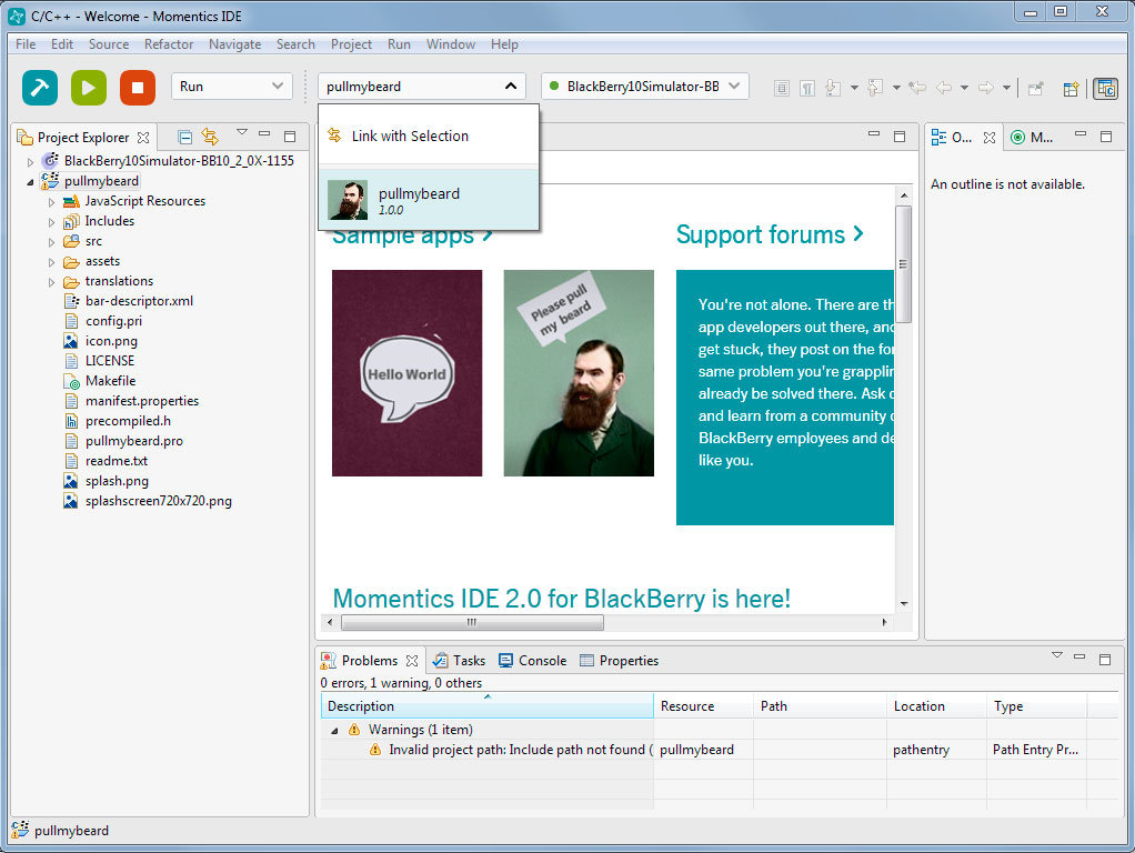
The IDE has also updated to show the pullmybeard app in the Project Explorer tab.

Running a BB10 Sample App in the Simulator


Once you have a BB10 app in the IDE, you can choose to run it on a Simulator or on a real BB10 device. Let's first look at how to run it in the Simulator.

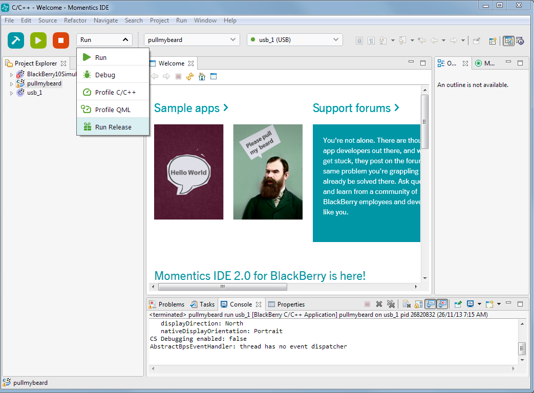
In the first drop down menu, make sure you have "Run" selected. Here you can also choose Debug which will let you step through the code while the app is running in case you need to debug the code to figure out what is going on in detail.

Using the second drop down menu at the top in the IDE, select the pullmybeard app you want to run.

The third drop down menu is used to select where you want to run the app. Make sure you still have BlackBerry10Simulator selected.


Attached Image: 28-selectApp.jpg


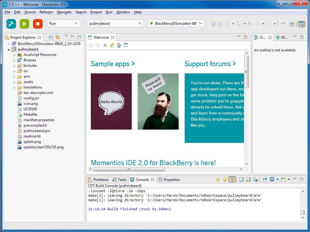
With the above options selected, click the first blue hammer button found at the top left of the IDE to build the application for the simulator. The console should output some messages and finally say "Build Finished".

Notice that in the Project Explorer you will now have a new section under pullmybeard that is named "Binaries". This is where your built app code is found that can be installed in the simulator to run.


Attached Image: 29-build.png


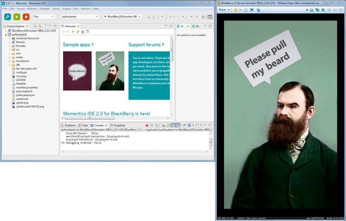
To run the app after the code has finished building, click the second green triangle button found in the top left of the IDE. This will cause the IDE to transfer the appropriate built files to the simulator and launch the application. You should now see the app running in the simulator.


Attached Image: 30-runningInSimulator.jpg


Turn your PC speakers ON and pull the beard using your mouse in the simulator. Press the left mouse button when your cursor is on the beard, drag your mouse down and then release the mouse button.

You can stop a running app by either clicking the third red square button in the IDE, or by minimizing the app and closing it in the simulator. To minimize an app in the BB10 OS, swipe up from the bottom of the screen and then click the X beside the minimized app name.

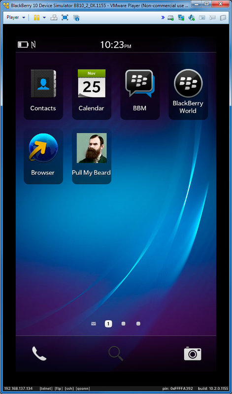
After an app is installed on the simulator it will remain there until you delete it. You can delete it by pressing and holding the left mouse button on the app icon for a few seconds. The app grid will start to pulsate and a delete icon will appear in the corner of the icon. Clicking the delete icon will delete the app from the simulator.

Note that if you make some code changes in the IDE and tell it to rebuild and run the same app, then the old version will be overwritten with the new version of the app before it will begin to run.

If you only want to run the app (and you are not interested in debugging it), you can restart the app by clicking on the app icon in the app grid.


Attached Image: 31-appAvailable.jpg


Analyzing a Running Application


The IDE can be used for more than just building and running applications on BB10, you can also use it to navigate the BB10 file system, you can copy and move files around, and you can watch how resources and memory is used in the simulator or real device.

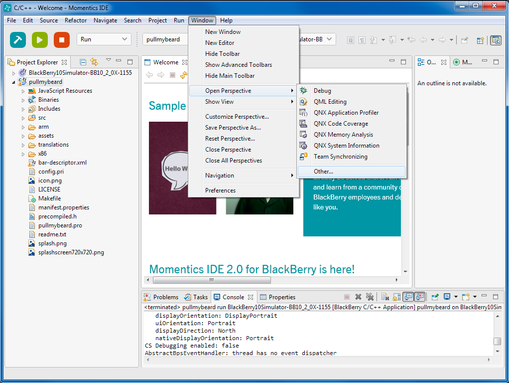
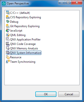
All of these functionalities are available through a QNX perspective in the IDE. To open a new perspective, select Window > Open Perspective > Other...


Attached Image: 32-perspective.png


In the new dialog that appears, select QNX System Information and then click OK.


Attached Image: 33-qnx.png


In the top right hand corner of the IDE you will now have a new perspective available to toggle between. When the QNX System Information perspective is selected, the bottom portion of the IDE will list a number of tabs including: System Summary, Process Information, Memory Information, Malloc Information, Target File System.

On the left side of the IDE, in the Target Navigator, you will see a listing of apps and services that are running on your simulator/device. You can click on one of these options and then choose one of the tabs (Memory Information) to see how much memory the selected application is using.

Another handy thing to know about applications is that anything that you install will become available in the Sandboxes folder. See image below.


Attached Image: 34-target.png


After installing the Pull My Beard application, you can see that there is a new entry there that contains the app executable, a config folder used to store settings, data, db, logs, etc. If your app generates log messages, you will be able to find the log file in the log folder. The app code that you run when you launch the application is found in the app directory. There you can view and modify the QML code if you wanted to.

Running an App on a Real BB10 Device


So far you have seen how to setup the BB10 Simulator and run a sample application on it. Now let's build the Pull My Beard application for a real BB10 device and run it there.

A simulator is good to get you started with development, but there are certain things that can be done much better or easier on a real device. For this reason, it is always better to try to run your app on a real device before releasing it in BlackBerry World.

If you still have the BB10 simulator running, close the VM Player as you won't need it and it can take up a lot of PC resources.

Also if you are still in the QNX System Information perspective from the last section, return back to the C/C++ perspective by clicking on the icon to the left of the QNX System Perspective icon in the top right hand corner of the IDE.

Open the Device drop down menu, and you will see that it lists "No Device (USB) Detected". Choose the Manage Devices... option to setup the IDE for a real device.


Attached Image: 35-deviceSetup.png


In the Device Manager dialog, select "Devices" in the top and choose the "Set Up New BlackBerry 10 Device" button.


Attached Image: 36-setup.png


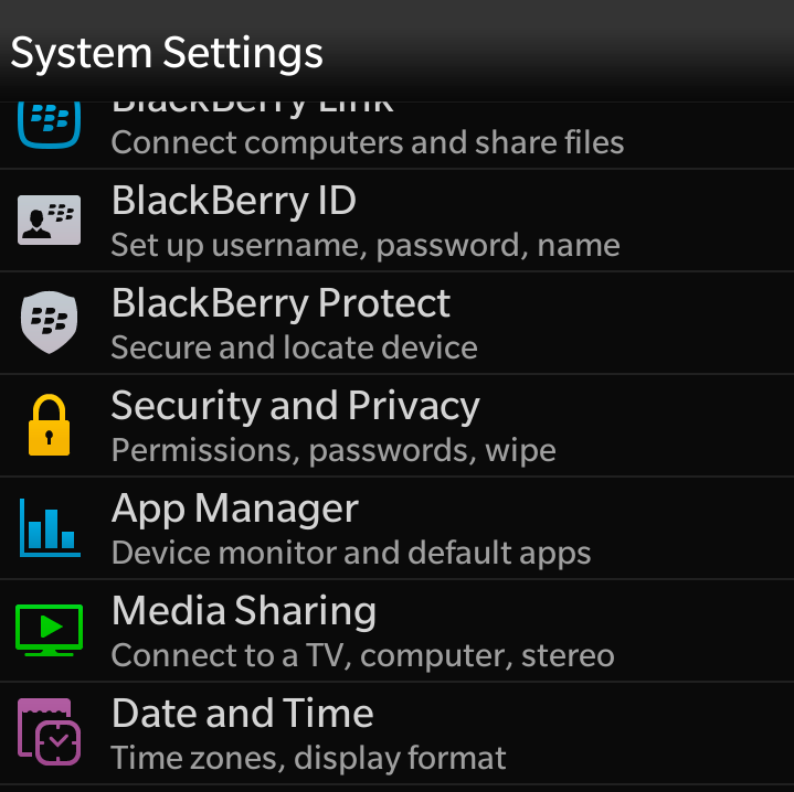
On the next screen you need to pair your device to the IDE. First of all you need to make sure that your device is running in "Development Mode". To put your device into development mode, swipe down from the top of the screen on your BB10 device to open the quick settings panel.


Attached Image: 37a-devMode.jpg


Click on the Settings button in the top left corner to open the system settings app.


Attached Image: 37b-devMode.png


Scroll down until you see the "Security and Privacy" option and click it.


Attached Image: 37c-devMode.png


Scroll down to the very bottom where you will see the "Development Mode" option and click it.


Attached Image: 37d-devMode.png


At the top of the screen there is a toggle button. Turn development mode ON by clicking on the toggle button. The device will ask you to set a device password if you don't have one set already.

Now that your device is ready in development mode, connect your BB10 device to your PC using a USB cable.

Back in the IDE, type in your device password and click the Next button to begin the pairing process.


Attached Image: 38-pair.png


After your device is paired with the IDE, you need to sign into your BlackBerry ID account so that you can generate a debug token. Fill in the input fields provided, and click the Get token button.


Attached Image: 39-token.png


A new dialog appears asking you to sign into your BlackBerry ID. If you don't have a BlackBerry ID account you can create a new one using the link at the bottom.


Attached Image: 40-login.png


After you sign into your account, you will be brought back to the IDE when your BlackBerry ID token has been successfully downloaded. Click the Next button.


Attached Image: 42-debug.png


You'll be back at the Device Manager dialog now with your newly listed BB10 device as "usb_1". The IDE will detect if you are missing any debug symbols and ask you to download them from the Internet. Click "Yes" and wait for them to download.


Attached Image: 43-symbols.png


If you go back to your BB10 device and look in the Development Mode section, you should see that a debug token has been installed on your device.


Attached Image: 44-deviceTokenDetails.png


A debug token is good for 10 days. This means if you install and run an app from the IDE on to your device, you will be able to use the app for only 10 days. After that, the app will become disabled. The IDE automatically updates the token on your device every time you run an app through the IDE. When you finish creating an app and you are ready to distribute it, you will want to create a final release which will be signed by your BlackBerry signing keys. Devices that don't have your debug token installed will not be able to run your app.

Ok, after your BlackBerry device is paired with the IDE and you have the debug symbols installed (note, it is always a good idea to restart the IDE after installing new symbols or a new API level) then you can run your app from the IDE on your BB10 device.

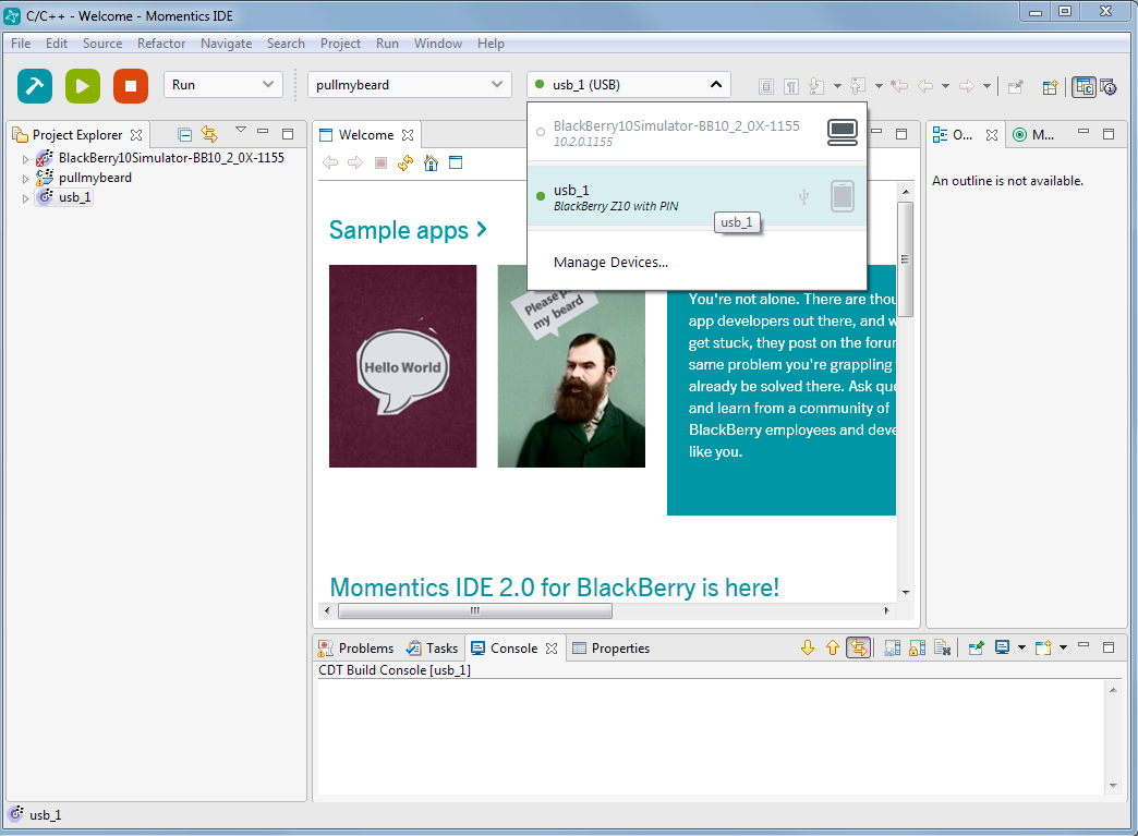
In the IDE, select usb_1 from the drop down list.


Attached Image: 45-selectDevice.png


Now press the blue build button to build the app code, and then click the green run button to install and run the app on your device.

To see what happens when your debug token expires, go back to the Developer Mode options and click the "Remove Debug Token" button.

Now try to run the Pull My Beard app from the app grid on your BB10 device and you'll notice that the app fails to launch.

Creating a Release Run


After you've fully tested your app and cleaned up any bugs you are ready to create a release version of your app. This is the version that you can upload to BlackBerry World to distribute to people around the world. The release version is signed by your BlackBerry signing keys and it doesn't depend on the debug token that expires after 10 days.

To create a release build, use the drop down menu and choose "Release Run".


Attached Image: 46-release.png


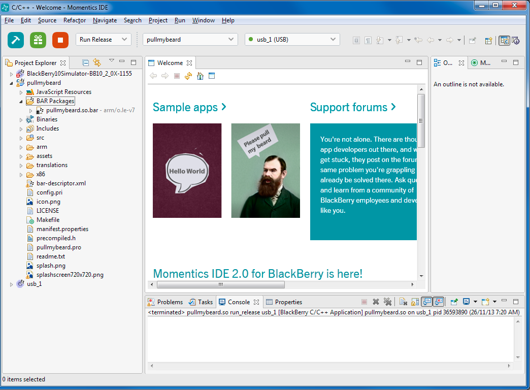
Select your app in the second drop down menu and click the build button. After the app is finished building you will see a new category under your app name in the Project Explorer called "BAR Packages". This is the bar file that contains your BB10 installation files that can be installed on anyone's BB10 device.

A bar file is just a zip file containing all the files that are needed to run your app. You can open a bar file in any zip file extractor program if you are interested in seeing what is inside it.


Attached Image: 47-bar.png


Conclusion


There you have it, I covered how to install the Momentics IDE on a PC and how to get it up and running for development using Cascades. We downloaded and installed the BlackBerry 10 simulator and saw how to control it using a separate Controller application. We then looked at how to download a sample application and import it into the IDE. We learned how to build and run a BB10 Cascades application on both the BB10 Simulator and on a real BB10 device. Along the way I hope you learned a few tips on how to view the BB10 file system, monitor memory usage of applications running on your device and also how to work with debug tokens and release builds.

If you are looking for detailed documentation on Cascades, the programming language used for native BB10 development, then have a look here: https://developer.blackberry.com/native/documentation/cascades/

If you have any questions or comments about this lesson send me an email, I'm interested to hear what you thought of it. Also if you have suggestions for additional BB10 lessons send them along to me!


Article Update Log


18 Feb 2014: Initial release

10 Things You Didn't Know You Needed from Crossplatform Mobile Game Engines

$
0
0
When 2 years ago I started looking for a crossplatform mobile game engine, it was really hard to find one that matched my needs, because as it turns out, I did not actually know what I needed. I was choosing them by completely different characteristic that proved to be irrelevant in the end.

For example, I wanted an engine which provided development in the language I already knew and was comfortable with. That actually put a very strict limitation and I was missing out on many great engines.

My second mistake was assuming that most popular engines would be the best. Yes, it is great if the engine has a large community and lots of resources, etc. But, in the end, those engines are overpriced, they usually force their own views and ways, and I was missing out on a lot of smaller popularity engines, that maybe did not have all the features in the world, but actually provided the ones I need.

So while searching and jumping from one engine to another, getting burnt by limitations I found, and struggling to find the one engine I wanted to work with, I started to lower my expectations and try out a couple of less popular ones, until someone on Twitter suggested me to try out Gideros (http://giderosmobile.com/).

At first, it seemed that Gideros did not have much to offer on the table comparing with lots of more popular investment backed engines, but it actually did contain all the features I needed, and even the features I did not know I needed, but now I can't live without them.

After being with Gideros more than 2 years now, I grew fond of it so much that I published a book on Gideros and even started working in team at Gideros to make the engine even better, contribute more, and add the other features I was missing for other projects.

10 Things You Didn't Know You Needed from Crossplatform Mobile Game Engines


1) It should be free to try


Of course the engine should allow you try itself for free, with as little friction as possible. And Gideros does just that. You can develop and even publish your apps for free (with a small Gideros splash screen). And to try it you don't need to do anything except click on the download link, no registration, nothing. How cool is that?

2) Auto scaling


One of the most awesome Gideros features is to provide different autoscaling modes. As in, you can make your images fit any screen, being either upscaled or downscaled. You can enable letterbox mode to upscale images so that they would be inside the screen with fixed aspect ratio and centered, or you can crop them and still keep the aspect ratio, or stretch by width, height or both. Lots of ways to combine with logical dimensions and experiment to find your best strategy for targeting different screen resolutions.

3) Auto image resolution


But sometimes when differences are too large, like between small android with 320x480 to iPad Retina, your upscaled pics will look awful, even with some antialising enabled, it won't be the same. But you can fix that using auto image resolution, which allows you to provide same images with different resolutions and then Gideros engine will pick the proper resolutions automatically based on which device your app runs. Combining this with auto scaling, there will be no problem you could not handle when targeting all from small phones to HD TVs on Ouya or GameStick.

4) Instant on device testing


I cannot stress enough how awesome this feature is. Basically when developing mobile games for different platforms, you would need to build apps and deploy them to try them out, or use simulators, which are usually so slow. Here, you can launch Gideros desktop player and run your app on it in an instance. Click play and it is running.

Wait that’s not all! Want to try out your app on device? Install Gideros Player on your device, and enter the player's IP into Gideros Studio on your PC. And same thing happens, you click play, and app is run on device instantly. No exporting. No building. No signing. No deploying! Instantly on device. That speeds up the development time, like 10 times or even more, especially in prototype level. This is something anyone should try out.

You just need to install Player on your device, and you can develop and test game on your iPad without Mac, through Windows PC, or vice versa.

5) Extending with plugins


When I was looking and different crossplatform engines, I was thinking it has to have it all. Oh boy how wrong I was. Firstly if an engine has it all, it is most probably so bloated, providing huge app files. And chances are, its API will be so fragmented, that some function would only work on one platform, others on other. It won't be developing once run anywhere anymore, it would be more like, write once adapt everywhere, which adds more work to it.

So no, Gideros does not have it all, but it came pretty close. It provides an option to write and use plugins (even for free members) to extend basically any platform specific functionality. No more road blocks, as it does not support this ad framework, or that service, etc. Just take and build it yourself, you're the king of your app's possibilities.

6) OOP


Game development is very difficult without a proper OOP model provided in the language/environment. It's not impossible, but when you are creating a game, there are a lot of objects there (notice word objects, already indicates the preferable development approach), and their properties overlap, so you can define them in classes, inherit properties, etc.
So when I was looking for game development in JavaScript, this is what usually provided lots of development problems - the lack of proper OOP. Although it is possible to achieve something similar in JavaScript, it usually felt unnatural.

Gideros uses Lua, which by default is also not an OOP language (while it allows lots of different OOP implementations), but Gideros also has a built in class system. And why is it good to have a one single built in class system, rather than allowing anyone to develop their own? Because then any class, any object that was developed by any Gideros developer, will be compatible with your own project, thus providing you with lots and lots of reusable code, not only between projects, but also between different developers. That has been a huge revelation to me, that it actually means a lot to a development community.

7) Full control of exported project


When exporting your project to platform specific app, Gideros does not compile for you an end app, but rather exports you a project meant to be used to build an end app. This feature could be arguably considered as con, because it makes you work with each native platform building workflow and learning it.
But I would want to say that learning the way it works for each platform, first makes you more engine independent, second provides more flexibility to your project, like adding an animated splash screen, and third provides the ways to create your own build workflows reusing dropbox, testflight deployments, etc.

8) Common interfaces


The more I hear that engine X created specific plugin for service Y, the more I understand how awful their API must be. Because you see, it's basically all about marketing. X can announce that they created plugin for Y. Y can announce that they now support X, but in the end, the developer has another class with similar functionality but different usage he needs to learn to work with.

What I found Gideros is doing, is actually creating common interfaces for similar stuff. For example, there is a common interface for Ads that allows you to implement lots of ad frameworks, using completely same workflow. And if you want to change from one ad framework to another, it is usually a question of changing a couple of lines, without changing the usage of interface much. Same goes for In-app Purchases and Controller support. Imagine having implemented a single controller interface and automatically supporting Xbox, PS3, OUYA, IOS7, ICade, Gametel, Moga, Green Throttle, etc controllers and systems without any additional work. That is just wow.

9) Encryption


I once saw a situation happen to a fellow developer, that someone disassembled his app and without even changing the code, simply replaced the graphics and republished multiple variations of copies of such app. Funny thing they did not even change the email address of the support form, thus the original developer was receiving in app support emails from the copied games.

Thus it is really important to not only encrypt your code, but also assets.

10) Community


No matter how good you are at developing, when learning something new, it is really important to have someone to ask for help, to learn more quickly. And Gideros has an awesome community that does just that. Just visit the forum with any questions regarding Gideros you might have and see for yourself ;)


title image

Skinned Mesh Animation Using Matrices

$
0
0
This article describes a method of animating skinned meshes using matrices.

Games often use animated characters which walk, run, shoot, etc. Those animated characters are often rendered using an animated skinned mesh. Such skinned meshes and animation sequences can be created using several modeling programs (such as Blender). Those models can then be exported in a format compatible with various API import routines. This article provides an overview of the animation process in the final application after that data has been imported ("loaded", "read in".) The process of modeling, rigging, animation, exporting or importing is not discussed.

Notes:
------------------------------
For conciseness, the term SRT is used as an abbreviation for the process of applying, in order, a Scale operation, a Rotatation operation, and a Translate operation. For most applications, that is the order in which those operations should be performed to achieve the expected results.

The order of matrix multiplicaiton varies among APIs. The order of matrix-matrix multiplicaitons and vector-matrix multiplications shown herein is that used by DirectX and assumes "row-vector" matrices. For instance:

// order of multiplication in DirectX
FinalVector = vector * ScaleMat * RotationMat * TranslationMat

In OpenGL, the order of those multiplications may be reversed, as OpenGL applications commonly use "column-vector" matrices. That is, to achieve a vector scaling followed by a rotation, followed by a translation, the equation would be:

// order of multiplication in OpenGL
FinalVector = TranslationMat * RotationMat * ScaleMat * vector

N.B., the mathematical end result of the operation is the same in both DirectX and OpenGL - a vector position that has been scaled first, rotated, and translated, in that order.

Animating a skinned mesh relies on the principle that scaling, rotating and translating (SRT) a position in space can be represented by a matrix. Further, an ordered sequence of SRTs can be represented by a single matrix resulting from multiplying a sequence of matrices, each representing an individual SRT. E.g.,

final-matrix = SRTmatrix1(rot1 followed by trans1) * SRTmatrix2( rot2 followed by trans2).

In that example, the final-matrix, when applied to a position, would result in a rotation of the position by rot1, followed by a translation (trans1), followed by a rotation (rot2), followed by a translation (trans2).

The Components of an Animated Skinned Mesh


"Animated" means moving or appearing to move as if alive.

"Skinned" means a mesh with a frame or "bone" hierarchy with which mesh vertices can be rendered at various positions in space to simulate movement - such as running, waving, etc.

"Mesh" means a collection of vertices (positions in space) forming faces (triangles, quads) to be drawn, perhaps in different orientations (SRTs).

What's a "bone?"


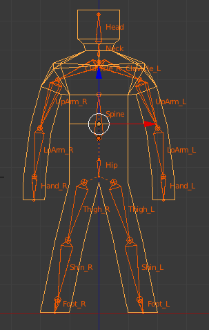
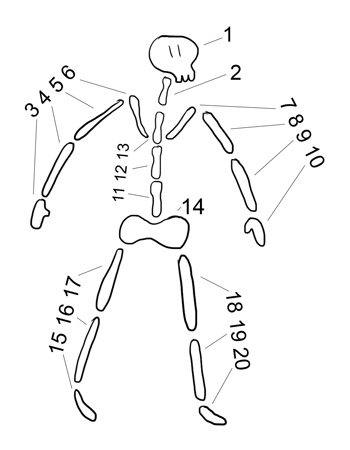
The term "frame" is used because it refers to a mathematical "frame of reference," or an orientation (SRT) with respect to (for instance) the world. The term "bone" is frequently used instead of "frame" because the concept can be used to simulate how a bone would cause the skin around it to move. If an arm is raised, the bones of the arm cause the skin surrounding the bone to move upward. However, the term "bone" implies a length associated with it. Bone frames used in the type of animation described in this article do not have an associated length. Though the "length" of a bone might be thought of as the distance between a bone and one of its child bones (lower arm bone with a hand bone 13 inches away), a bone as used for skinning meshes may have more than one child bone, and those child bones need not be at the same distance from the parent. For instance, it is not unusual for a human character to have a neck bone, and right and left shoulder bones, all being children of a spine bone. Those child bones need not be at the same distance to the spine bone.


Attached Image: child bones of the spine.png


In a common frame hierarchy, every frame except the root frame has a parent frame. That allows the entire hierarchy to be scaled, rotated and translated with a single matrix. Take a look at the frame hierarchy below. An indentation of a frame name immediately below another frame indicates a child-parent relationship. E.g., the Hip frame is a child of the root frame. The Left Thigh frame is a child of the Hip frame. Further notice that the Spine frame is at the same level of indentation as the Hip frame. That indicates that the Spine is a sibling of the Hip frame, and a child of the Root frame. If the root frame has an SRT applied to it, that SRT propagates down the entire tree, from child to child. E.g., if the root frame is rotated, the hip is rotated by the root frame, the left thigh is rotated by the hip, etc. Similarly, if the root frame is translated, the entire hierarchy is translated.

In an animated skinned mesh, SRT matrices may be applied to any frame in the hierarchy. That SRT will be propagated only to the frame's children, through the frame's children to their children, etc. There is no effect on the parent of that frame. In that way, the Left Upper Arm can be rotated upward in a waving motion. The Left Lower Arm and Left Hand will rotate upward also. However, the Left Clavicle, the Spine and the Root frame will not move, and the waving motion will appear as one might expect.

An example frame hierarchy

Root frame

Hip

Left Thigh

Left Shin

Left Foot

Right Thigh

Right Shin

Right Foot

Spine

Neck

Head

Left Clavicle

Left Upper Arm

Left Lower Arm

Left Hand

Right Clavicle

Right Upper Arm

Right Lower Arm

Right Hand


It should be noted that other objects such as building cranes, or an office chair where the seat and chair back can rotate independently, can be animated in precisely the same fashion. However, the advantage of the skinning process is that the mesh, with proper bone-weighting of the vertices, can appear to deform smoothly as if it were bending in a non-linear fashion. For instance, when an arm is raised, it appears that the skin between the chest and the shoulder stretches. If a hand is rotated, it appears that the skin between the lower arm and the hand stretches and rotates.

This article discusses frames (bones) which are implemented in skinned mesh animation with matrices. Each frame, during the animation process, has several matrices associated with it in the course of a single render cycle. Each bone, for instance, has an "offset" matrix related to that bone's SRT with respect to the root frame; each bone has a set of animation "keys" (matrices) used to orient the bone with respect to its parent bone during animation; each bone has an animation matrix and a "final" matrix. That may appear to be complicated, but can be understood by considering the process one step at a time.

The Frame Structure


Before continuing, consider an example of how a "frame" may actually be represented in code. Pseudo-code is used which looks quite like C or C++, but hopefully can be converted to other languages a programmer may be more comfortable with.

struct Frame {
    string Name; // the frame or "bone" name
    Matrix TransformationMatrix; // to be used for local animation matrix
    MeshContainer MeshData; // perhaps only one or two frames will have mesh data
    FrameArray Children; // pointers or references to each child frame of this frame
    Matrix ToParent; // the local transform from bone-space to bone's parent-space
    Matrix ToRoot; // from bone-space to root-frame space
};

Normally, each frame has a name. In the hierarchy above, all of the frames (Root, Hip, Left Thigh, etc.) would each have a frame like the above, and Name would correspond to the name in the hierarchy.

The other members of the frame structure and their uses will be described in more detail later in the article.

Animation Data and How It's Used


The data below indicates what information is needed to animate a skinned mesh. Not all of the data is contained in the frame hierarchy structures. Generally, the frame hierarchy contains data describing the bone structure, the mesh structure, and relationships between bones and mesh vertices. All that data represents the skinned mesh in a rest pose.

Animation data is commonly stored and accessed separately. That is intentional as a set of animation data represents a single action for the mesh, e.g., "walk," "run," etc. There may be more than one of those animation sets, but each set can be used to animation the same frame hierarchy.

The total data needed for animation of a skinned mesh is comprised of:

* A mesh in a "pose" or "rest" position, possibly contained in a frame.
* A frame hierarchy. The hierarchy is normally comprised of:

- a root frame
- for each frame, a list or array of pointers to that frame's children's frames.
- for each frame, an indication if the frame contains a mesh
- for each frame, one or more matrices for storing frame-related SRTs

* various arrays of influence bone data

- for each influence bone, an offset matrix
- for each influence bone, an array of vertex indices and weights for the vertices which the bone "influences."

* an array of animations. Each animation is comprised of:

- an indication of which bone the animation applies to
- an array of "keys." Each key is comprised of:

- a tick count indicating the "time" in the animation sequence the key applies to
- a matrix (or a set of individual SRTs) for that tick count.

* An indication of how many ticks should be processed per second (ticks-per-second)

Note:  in some cases, all that data may not be contained in the data file(s) for the mesh to be animated. Some formats, for instance, do not provide an offset matrix. That matrix can be calculated from other information. The offset matrix is discussed below.


The Mesh


The mesh data is comprised of an array of vertices, positions relative to the root frame (or to a frame containing the mesh), along with other data such as normal vectors, texture coordinates, etc. The vertex positions are normally in a pose or rest position. I.e., not in an animated position.

If the mesh data is the child of a frame other than the root frame, the skinning process must account for that. That is considered in the discussion of the Offset Matrix below.

Animated meshes are most often rendered in a shader or effect. Those shaders expect as input vertex information in a particular order during rendering. The process of converting per-vertex data as-imported to a vertex format compatible with a particular shader or effect is beyond the scope of this article.

Initializing The Data


With an idea of the data that's needed for skinned mesh animation, here's an overview of the process that makes animation possible. A lot of the required data is loaded from an external file. A frame hierarchy is created and, referring to the Frame structure above, filled with at least the following data: Name, MeshData (not all frames), Children (if the frame has any), and the ToParent matrix.

The ToRoot matrix for each frame is initialized as follows:

// given this function ...
function CalcToRootMatrix( Frame frame, Matrix parentMatrix )
{
    // transform from frame-space to root-frame-space through the parent's ToRoot matrix
    frame.ToRoot = frame.ToParent * parentMatrix;

    for each Child in frame: CalcToRootMatrix( Child, frame.ToRoot );
}

// ... calculate all the Frame ToRoot matrices
CalcToRootMatrix( RootFrame, IdentityMatrix ); // the root frame has no parent

Recursive functions such as CalcToRootMatrix can be a little difficult to grasp at first. However, the following expansion of the process will hopefully show what's happening:

frame.ToRoot = frame.ToParent * frame-parent.ToParent * frame-parent-parent.ToParent * ... * RootFrame.ToRoot

Some of the data needed for animation will apply only to those bones which influence mesh vertices. During the rendering process, that data will be accessed by bone index, not by bone name. A SkinInfo object or function, using the array of bone influence data, provides the number of influence bones in that array [ SkinInfo.NumBones() ]and can return the bone index given the bone's name [ SkinInfo.GetBoneName(boneIndex) ]. A more detailed decription of SkinInfo is beyond the scope of this article.

The initialization process also creates an array of "offset" matrices, a matrix for each influence bone. As not all frames in the hierarchy influence vertices, that array is smaller than the number of frames, and is sized to hold SkinInfo.NumBones().

A Slight Diversion from the Initialization Process


Though not part of the initialization process, understanding what the frame's TransformationMatrix is used for will help to understand why an array of "offset" matrices is needed for animation.

The Frame TransformationMatrix is filled each render cycle using the animation arrays. An "animation controller" object or function uses the animation data to calculate those transforms and stores the result in each frame's TransformationMatrix. That matrix transforms vertices from a bone's reference frame to the bone's parent's animated reference frame. Similar to the ToParent matrix, which applies to the "pose" position, this matrix applies to an "animated" position - how the mesh will appear during animation. One can think of this matrix as being "how the bone will change from pose position to animated position."

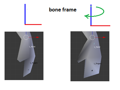
Consider the following situation. During an animation, the character's hand is to be rotated slightly by an influence bone.


Attached Image: rotate2.png
Bone-frame Rotation


If the bone's TransformationMatrix is applied to a vertex which it influences, the vertex position, being in root-frame space, will rotate instead in root-frame space.


Attached Image: rotate1.png


Yet another matrix is needed which will transform the vertex into bone-space so the rotation can be applied properly.

Enter..

Back into Initialization - The Offset Matrix


Note:  The offset matrix is already provided by many file formats and explicit calculation of the offset matrix for each influence bone is unnecessary. The information below is provided for the purpose of understanding the purpose of the offset matrix.


For a vertex to be properly transformed by an influence bone during animation, it must be transformed from 'pose' position in the root-frame to the influence bone's pose frame. Once transformed, the bone's TransformationMatrix can be applied to result in "how the vertex will change from pose position to animated position" as shown in the Bone-frame Rotation shown above. The transformation for a vertex to bone-space in "pose" position is called the "offset" matrix.

IF the mesh is in a parent-frame other than the root-frame, it has to transformed from that parent-frame into root-frame space before it can be transformed from " 'pose' position in the root-frame" as described in the preceding paragraph. Luckily enough, that's easily accomplished using the mesh's parent-frame ToRoot matrix.

Each influence bone frame has a ToRoot matrix, but that transforms from bone-space to root-frame space. The inverse of that transformation is needed. Matrix math provides just such a conversion - the inverse of a matrix. In very simple terms, whatever mulitplying a vertex by a matrix does, multiplying a vertex by the inverse of that matrix does the opposite.

The array of offset matrices can be calculated as follows:

// A function to search the hierarchy for a frame named "frameName" and return a reference to that frame
Frame FindFrame( Frame frame, string frameName )
{
    Frame tmpFrame;

    if ( frame.Name == frameName ) return frame;
    for each Child in frame {
        if ( (tmpFrame = FindFrame( Child, frameName )) != NULL ) return tmpFrame;
    }
    return NULL;
}

// Note: MeshFrame.ToRoot is the transform for moving the mesh into root-frame space.
function CalculateOffsetMatrix( Index boneIndex )
{
    string boneName = SkinInfo.GetBoneName( boneIndex );
    Frame boneFrame = FindFrame( root_frame, boneName );
    // error check for boneFrame == NULL if desired
    offsetMatrix[ boneIndex ] = MeshFrame.ToRoot * MatrixInverse( boneFrame.ToRoot );
}

// generate all the offset matrices
for( int i = 0; i < SkinInfo.NumBones(); i++ ) CalculateOffsetMatrix( i );

A pseudo-expansion of an offset matrix is as follows:

offsetMatrix = MeshFrame.ToRoot * Inverse( bone.ToParent * parent.ToParent * ... * root.ToParent )

A further pseudo-expansion including the Inverse would be:

offsetMatrix = MeshFrame.ToRoot * root.ToSomeChild * Child.ToAnotherChild * ... * boneParent.ToInfluenceBone

As the offset matrices are calculated solely from "pose" position data, they only need to be calculated once, and are used every render cycle.

The Root Frame


The "root" is a frame to which all other bones are parented in a hierarchical manner. That is, every bone has a parent or a parent's parent (etc.) which is the root frame.

If the root frame is scaled, rotated and translated, the entire hierachy will be scaled, rotated and translated.

The root frame may be positioned anywhere with respect to the mesh. However, for an animated character mesh, it is more convenient for it to be located at the character's midline, e.g., between the feet, as if it were resting on the ground. For flying objects, it may be more convenient for the root frame to be located at the center-of-gravity for the character. Those details are determined during modeling.

The root frame has no parent bone. It has only child bones.

A Bone and It's Children


Some bones have associated with them a set of vertices which they influence. "Influence" means that a vertex will move when the bone is moved. For instance, a lower arm bone may influence the vertices in the mesh from the elbow to the wrist. When the lower arm bone rotates (with respect to the upper arm), those vertices rotate with it. The lower arm bone movement will also result in the hand bone and finger bones moving. The vertices influenced by the hand and finger bones will then also move. Vertices comprising the upper arm or other parts of the mesh do not move with the lower arm.

As implied above, some frames in the hierarchy may not influence any vertices. They can, perhaps, still be called "bones," but not "influence bones." Those frames still orient their child frames during animation, and TransformationMatrix calculations are still done for every frame in the hierarchy.


Attached Image: skinned mesh.png
The mesh and bone hierarchy in pose position


Bone Influences and Bone Weights


This data is an array specifying which bone influences which vertex, and by how much (by what weighting factor). For each bone, that data is several pairs of numbers: a vertex index and a floating point number between 0 and 1. The vertex index is the position in the mesh vertex array (positions for the mesh in pose position). The weight is "how much" the vertex position will be moved relative to the bone when the bone moves. If several bones influence the same vertex, the sum of the bone weights must equal 1 (one) for proper rendering. E.g., if 2 bones influence a vertex and the bone weight for one of the bones is 0.3, the other bone weight must be 0.7. A bit of code in the final vertex position calculation makes use of that requirement. See below.

This data is commonly contained in and maintained by a SkinInfo object. As mentioned above, details of how a SkinInfo object performs its tasks are beyond the scope of this project.

The Animation Process


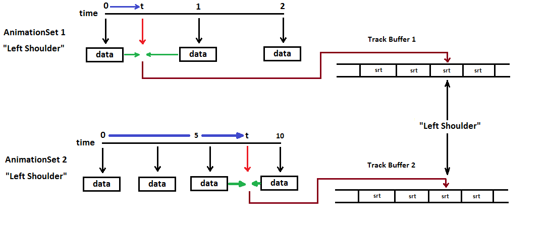
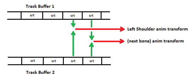
The discussions above describe the frame hierarchy in "pose" position, ready for animation. The data needed for animating the mesh in real time is normally separate from the hierarchy data. That separation is intentional. A set of animation data represents a single action for the character: running, walking, etc. By separating the animation data from the frame hierarchy, several sets of animation data, each of which can be applied to the "pose" position, can be used to provide changing the action for the character from running to walking, etc., or even apply then simultaneously - e.g., "shoot-while-running."

The animation data is commonly stored with and maintained by an AnimationController object, possibly just a series of application functions. Details of the workings of an Animation Controller are beyond the scope of the project. However, some of the tasks that the AnimationController performs are described below.

Animation data for a single animation is called an animation set and is normally comprised of an array of frame animations. The following pseudo-code is arranged to better provide an understanding of the structure and shouldn't be construed as compilable code. An animation set may be organized similar to the following:

struct AnimationSet {
	AnimationArray animations;
}

struct Animation {
	string frameName; // look familiar?
	AnimationKeysArray keyFrames;
}

struct AnimationKey {
	TimeCode keyTime;
	Vector Scale, Translation;
	Quaternion Rotation;
}

Animation Keys


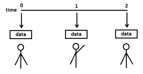
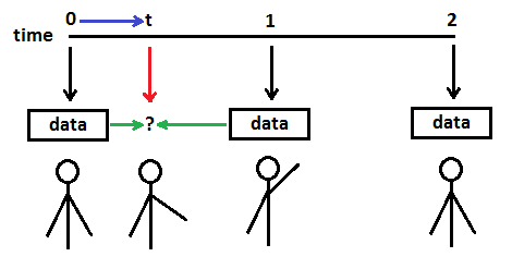
Each frame has associated with it a set of animation "keys." Those keys define the frame's orientation with respect to its parent's orientation (NOT the root frame) at a particular time during the animation sequence. The "time" may be represented as an integer number, a count of clock ticks. (Time may also be a floating point number, representing the time relative to the beginning of the animation). There are usually a minimum of 2 such "timed" keys, one for the start of the animation (count=0), and one for the end of the animation (count = number of ticks for the entire sequence). In between the start and end counts, there may be keys at various counts during the animation, defining a change in the bone's orientation since the last key (or time within the sequence.) E.g., for a 100 count animation: at count 0, the arm bone is lowered. At count 50, the arm bone is raised. At count 100, the arm bone is lowered back to its original position. During the animation, the arm starts lowered, raises smoothly to its raised position at count 50, and lowers smoothly to its original position at count 100.

Keys are often stored as individual vectors for scale and translation, and quaternarions for rotation, to make the process of interpolating keys easier. That is, using the above 100 count animation example, the SRT of the bone at count 25 will be interpolated (calculated) somewhere "between" the key at count 0 and the key at count 50. If the key is stored as vectors and quaternarions, a matrix is calculated from interpolated values for the scale, rotation and translation of the "previous" key and the "next" key (in the example, from the "previous" count 0 key and the "next" count 50 key.) Those interpolated values are commonly calculated as a NLERP (Normalized Linear IntERPolation) or SLERP (Spherical Linear intERPolation) of the quaternarions and LERP (Linear intERPolation) of the vectors. As the rotation change is normally very small between successive ticks, NLERP produces satisfactory results and is faster.

If the keys are instead stored as matrices, the key matrices for the "previous" key and "next" key are each decomposed into a quaternarion and two vectors. The quaternarions are SLERPed, the vectors are LERPed, and a matrix is calculated from the resulting quaternarion and vectors. This is not a reliable practice, however, as decomposing a matrix which includes non-uniform scaling may produce erroneous results.

When the matrix for a frame is calculated (for a particular count in the animation sequence), that matrix is stored in that frame's Frame structure as the TranformationMatrix.

As mentioned, animation data is stored and maintained separately from the frame hierarchy, so storing each frame matrix in the appropriate place can be done by using the FindFrame() function exampled above.

In each render cycle, the AnimationController may perform something like the following:

function CalulateTransformationMatrices( TimeCode deltaTime )
{
	TimeCode keyFrameTime = startTime + deltaTime;
	for each animation in AnimationSet:
	{
		Matrix frameTransform = CalculateFromAnimationKeys( keyFrameTime, animation.frameName );
		Frame frame = FindFrame( rootFrame, animation.frameName );
		frame.TransformationMatrix = frameTransform;
	}
}

Ticks Per Second


The skinned mesh will be animated in real time to present to the user. "Real time" is in seconds, not tick counts. If a 100 count animation (raise and lower an arm) is to take 3 seconds, then ticks-per-second will equal 100 ticks / 3 seconds, or about 33 ticks per second. To start the animation, the tick count is set to 0. During each render of the scene, the delta-time since the last render (often just a few milliseconds) is multiplied by ticks-per-second, and the tick count is incremented by the value. For an animation that is intended to cycle, e.g., continual waving of the arm, the tick count must be adjusted. That is, as time passes, the tick count will eventually exceed 100. When that occurs, the tick count is decremented by 100, and the process continues. That is, if the tick count is incremented to 107, the tick count is adjusted to 7, and the animation repeats.

Yet More Matrices Must Be Calculated


Really? REALLY??

Yes, more matrix calcs.

The offset matrix discussed above transforms vertices to frame-space, where the TransformationMatrix for that frame can be applied to animate the vertex in frame-space. The task now is to transform the vertex from frame-animated-space to root-frame-animated-space, so it can be rendered.

The process of calculating the transform for frame-animated-space to root-frame-animated-space can be done which is very similar to the CalcToRootMatrix function which transform from "pose" frame-space to "pose" root-space. The following calculates a transform for "frame-animated-space" to "root-frame-animated-space." Rather than building another entire array to hold the root-frame-animated-space transform for each frame, consider: the Frame.TransformationMatrix can just be converted from frame-space to root-space.

// given this function ...
function CalcCombinedMatrix( Frame frame, Matrix parentMatrix )
{
    // transform from frame-space to root-frame-space through the parent's ToRoot matrix
    frame.TransformationMatrix = frame.TransformationMatrix * parentMatrix;

    for each Child in frame: CalcCombinedMatrix( Child, frame.TransformationMatrix );
}

// ... calculate all the Frame to-root animation matrices
CalcCombinedMatrix( RootFrame, IdentityMatrix );

Are We There Yet?


Getting really close, but we don't have all the information we need in one place yet.

A vertex position can be transformed into frame-pose-space with the Offset matrix.

A vertex position can be transformed from frame-animated-space to root-animated-space with the Frame.TransformationMatrix.

For use by the shader (or other rendering routine), we need an array of matrices which will do both of the above operations. However, we need only the matrices for influence bones.

So, yet any another array of matrices called FinalMatrix, sized to hold SkinInfo.NumBones(), is created. However, it need be created only once as it can be reused every render cycle.

Calculating the final transforms can be done as follows:

// Given a FinalMatrix array..
function CalculateFinalMatrix( int boneIndex )
{
    string boneName = SkinInfo.GetBoneName( boneIndex );
    Frame boneFrame = FindFrame( root_frame, boneName );
    // error check for boneFrame == NULL if desired
    FinalMatrix[ boneIndex ] = OffsetMatrix[ boneIndex ] * boneFrame.TransformationMatrix;
}

// generate all the final matrices
for( int i = 0; i < SkinInfo.NumBones(); i++ ) CalculateFinalMatrix( i );

How It All Works Together


We're finally ready to actually render the animated skinned mesh!

For each render cycle, the following sequence takes place:

1. The animation "time" is incremented. That delta-time is converted to a tick count.

2. For each frame, a timed-key-matrix is calculated from the frame's keys. If the tick count is "between" two keys, the matrix calculated is an interpolation of the key with the next lowest tick count, and the key with the next higher tick count. Those matrices are stored in a key array.

3. When all the frame hierarchy timed-key-matrices have been calculated, the timed-key-matrix for each frame is combined with the timed-key-matrix for its parent.

4. Final transforms are calculated and stored in an array.

5. The next operation is commonly performed in a vertex shader as GPU hardware is more efficient at performing the required calculations, though it can be done in system memory by the application.

The shader is initialized by copying the FinalMatrix array to the GPU, as well as other needed data such as world, view and projection transforms, lighting positions and paramaters, texture data, etc.

Each mesh vertex is multiplied by the FinalMatrix of a bone that influences that vertex, then by the bone's weight. The results of those calculations are summed, resulting in a weight-blended position. If the vertex has an associated normal vector, a similar calculation and summation is done. The weighted-position (see below) is then multiplied by world, view and projection matrices to convert it from root-frame space to world space to homogeneous clip space.

As mentioned above, proper rendering requires that the sum of the blend weights (weights for the influence bones) for a vertex sum to 1. The only way to enforce that assumption is to ensure that the model is created correctly before it is imported into the animation application. However, a simple bit of code can help and reduces by 1 the number of bone weights that must be passed to the vertex position calculations.

Calculating A Weighted Position

// numInfluenceBones is the number of bones which influence the vertex
// Depending on the vertex structure passed to the shader, it may passed in the vertex structure
// or be set as a shader constant
float fLastWeight = 1;
float fWeight;
vector vertexPos( 0 ); // start empty
for (int i=0; i < numInfluenceBones-1; i++) // N.B., the last boneweight is not need!
{
   fWeight = boneWeight[ i ];
   vertexPos += inputVertexPos * final_transform[ i ] * fWeight;
   fLastWeight -= fWeight;
}
vertexPos += inputVertexPos * final_transform [ numInfluenceBones - 1 ] * fLastWeight;

Summary


Data for a skinned mesh is loaded into or calculated by an application. That data is comprised of:
- mesh vertex data. For each vertex: positions relative to a frame of the bone hierarchy
- frame hierarchy data. For each frame: the frame's children, offset matrix, animation key frame data
- bone influence data - usually in the form of an array for each bone listing the index and weight for each vertex the bone influences.

Note:  Many of the operations described above can be combined into fewer steps and otherwise simplified. The intent of this article is to provide descriptions of the processes involved in animating skinned meshes using matrices, not necessarily in an efficient fashion.


Article Update Log

13 Feb 2014: submitted draft
15 Feb 2014: added weighted vertex position calc code.
15 Feb 2014: submitted for moderator approval
21 Feb 2014: revised tags. Added information regarding mesh "to-root" transform
24 Feb 2014: revised to include more pseudo-code examples and images.
25 Feb 2014: Moderator approval received. Went into peer review stage.
26 Feb 2014: Added NLERP to keyframe interpolation ( credit: member Alundra )

Fast GUI Rendering using Texture2DArray

$
0
0
A lot of the times when working with custom game engines the UI has always been a struggle, both when it comes to usability and performance. To combat this I have worked a lot with GUI rendering in mind when structuring the engine, and with this article I want to share my results.

Important

  • The focus in this article is the rendering
  • We will be using Texture2DArray (DirectX 10 feature, pretty sure OpenGL has similar features)
  • This article will not be a performance comparison with other UI libraries
  • It is a result of working on a game
  • No source code/download is available
  • Some of source code tags will be in lua(ish) code because there is no lua syntax formatter the comments will be // instead of --

Ideas and Different GUI Styles


Immediate and Traditional Mode GUI


Immediate Mode GUI has grown to be quite common nowadays when it comes to realtime applications and for all the right reasons. It is easy to setup and easy to modify but it comes with a price.

// during render (or maybe update but never seen that)
// this will also be drawn in this function, so if we dont call this
// function the buttons does not exist anymore

do_button("my label", x, y, function() print("I got clicked") end)

Pros
  • Easy to create, modify and remove without restarting etc..
  • Really easy to make basic GUI elements
  • Less amount of code to write
Cons
  • Harder to maintain good ordering, so controls behind other controls could get activated instead
  • Things that require some kind of state and a lot of input data get complicated to implement
  • Input is usually delivered during game updates and not when rendering, can make for strange behavior when clicking stuff
  • You tend to pay with performance for better usability
Traditional Mode GUI takes longer to setup and it is hard to change but it tends to be more stable and when it comes to advanced UI controls it can get tricky to implement with immediate mode.

// during some kind of init of a scene for example
    
local button = create_button("my label", x, y)
button:set_callback(function() print("I got clicked") end)
    
// later in render (this will draw all gui elements we have created)
    
draw_gui()

Pros
  • You know about all your controls before you start to draw/update them
  • Complicated controls with a lot of state and transformation/inheritance gets easier
  • Input handling gets more natural and stable
Cons
  • A lot more code needed
  • Hard to modify
  • Annoying to write and maintain (personal opinion)
For a simple control like a button both of the methods looks good, but for something like a scrollable listbox with a lot of items it can get messy really quick.

The reason I wanted to bring this up is because when using the traditional method the draw_gui function knows about all the GUI elements that will be drawn so it can make optimizations like a better draw order and separate them into groups depending on state changes (texture switches) etc..

The immediate GUI kinda lacks in this department and when rendering a button with text on it, we cannot assume that we can render the button first and then the text later on in another batch.

Mixing Immediate Mode with Traditional Mode


Since I like the Immediate mode GUI but wanted to have the benefits of the non immediate as well I have created a mixed kinda style that allows me to create advanced listboxes, windows, inputboxes while still drawing them in immediate mode.

// here are two versions of the immediate mode that do require an id
// but the id just need to be unique per scene
ui_button("button-id", "my label", onclick):draw(x, y)
ui_button({id = "button-id", label = "my label", onclick = print}):draw(x, y)
    
// this is what you do if you want to create the button beforehand
// this becomes useful when dealing with listboxes and more advanced controls
local button = ui_button({label = "my_label", onclick = print})
    
// in both cases the control comes to life when calling the draw function
button:draw(x, y)

Doing the UI in this way gives us all the functionality from the immediate mode, except that if we stop rendering an element we could end up with some state associated with it, but it will disappear and does not receive any further input. So basically we have the per element drawing and control of an element, but we also have a state associated with each control so we can make more advanced controls. This state allows us to poll input in the update loop instead of when rendering, and we can do the hidden update in reverse rendering order giving us the ability to ignore elements hidden under something.

While this is all good we still have the performance problem to tackle, we will do this by using extensive vertex buffering combined with texture arrays and texture sheets of specific sizes.

Technical Goals for the Mixed GUI


To create the Mixed UI system we need to achieve a few technical feats
  • Being able to have good performance even when elements have a very strange draw order
  • We cannot modify the draw order
  • Text and sprites/textures must be rendered without switching shader or adding a new draw calls
To meet these requirements we can conclude that we need a 'pretty' good draw_rect routine that can have different properties and textures without creating new draw calls.

Texture Arrays


This is a relatively new feature that allows us to use different textures in a shader depending on an input index that can come from a constant buffer
(this could be simulated with mega textures like 4096x4096)

The restriction with a texture array is that all textures in it must have the same width, height and format, so to make it a bit easier to manage I created a texture pool that holds a separate texture array for each combination of (width, height and format). Then I can just query the texture pool using any texture and if that texture has not been used before and does not fit in any of the existing texture arrays, we create a new texture array and load the texture in it and return (id 0) along with binding the new texture array object. If we had asked to bind a second texture with the same size it would just leave the current texture array active but update it with the new texture and return (id 1)

You could improve a lot upon this by merging smaller sized textures to a bigger one and add uv offsets, so you would end up with, let's say, mostly 1024x1024 textures in a long array.

Text Rendering


A specific font is stored on 1024x1024 texture and it contains all the different sizes packed as well. So for example calibri normal, bold and italic would be three 1024x1024 textures filled with glyphs rendered with various sizes.

An example of a packed font with different sizes, this is far from optimal right now since you can pack bold and italic variants as well and have a better packing

GUI Rendering


This is working in the same way as font rendering by storing all the graphics on a single texture that is 1024x1024

Putting it all together


Putting the font and UI rendering together we get x amount of 1024x1024 textures that we can put in an array. Then, when we select what texture we want to use, instead of switching textures and creating a new draw call we just insert the texture index to a constantbuffer and with every vertex supply the the index in the constantbuffer that has information about which texture we want to use.


Attached Image: gui.jpg Attached Image: font_result.jpg


Results of Using the Mixed GUI Implementation


Since this article is aimed at the rendering part of the GUI implementation, I will not put any focus on how the buttons, inputboxes, listboxes, sliders etc... are working. Maybe in another article.

This is an image I rendered from my engine that shows 100 buttons and 10 input boxes, the most interesting part is the number of draw calls made and the vertex count.


Attached Image: mixed_texture_with_text.png

  • draw calls for complete scene = 5
  • vertex count for complete scene = 8336
Here you can see switching from different text sizes have no impact on draw calls either


Attached Image: tex_renderingt.png

  • draw calls for complete scene = 5 (same as before)
  • vertex count for complete scene = 3374
This button & inputbox image was composed using code chunks like this one

// the push and pop is a stack system of render states and in this case
// it keeps the translation local to between them
push()
    
for i = 1, 10, 1 do
                 
    // this is the only place that knows about this textbox
    // it is not created in some init function, but we need the id
    // so it can keep track of itself the next time it gets drawn
    // after the first call the ui_textbox function will return the same
    // object
    ui_inputbox({id = i, value = string.format("input #%i", i)}):draw()
    
    // this will adjust each element 40 units down from the last one
    add_translation(0, 40)
    
end
    
pop()
    
    
// ui_textbox draw function would then look something like this
function draw(self)
   
	local width = self.width
    local height = self.height
    
    set_blend_color(1, 1, 1, 1)
    
    // set texture for complete gui texture sheet
	set_texture(gui_texture_id)
    draw_rect(...) // here the uv data would go in to grab the right part
    
    // set font, and this will trigger another set_texture internally
    set_text_font("arial.ttf")
    set_text_size(16)
    set_text_align(0, 0.5)
    
    // this function is essentialy just calling multiple
    // draw rects internally for each character to be drawn
    draw_text_area(text, 0, 0, width, height)
end

Implementation in C++ Using HLSL Shaders


Here we bind a texture object to the renderer and it will check in the active texture pool what texture is currently being used and either flush or just swap the active texture index

void IntermediateRenderer::bind_texture(Texture * texture)
{

    // this is a texture pool that contains several arrays of similar sized textures
    // lets say we want to bind texture A and that texture already exists in in the pool
    // then if we have a different array bounded we must flush but otherwise we just use 
    // another index for the next operations since texture A was already in the 
    // current active array texture
	auto mat = materials.get_active_state();
    
    if (texture == NULL)
    {
        // we dont need to unbind anything just reduce the impact of the texture to 0
        mat->texture_alpha = 0.0f;
    }
    else
    {
        unsigned int texture_index = 0;
        if (texture_pool.bind(texture, &texture_index, std::bind(&IntermediateRenderer::flush, this)))
        {
            // this means we flushed
            // this will start a new draw call
            
            // refresh the state, usually means we grab the first
            // material index again (0)
            mat = materials.get_active_state();
        }
        
        // just set the constant buffer values
        // and unless we flushed nothing will change
        // we will just continue to build our vertex buffer
        
        mat->texture_index = reinterpret_cast<float>(texture_index);
        mat->texture_alpha = 1.0f;
    }
}

Since we do use bitmap font rendering we can use the same rendering function when drawing a letter, as when we would draw any other textured rect. So the next step would be to create a function to render this textured rect efficiently.

Here is my implementation in c++ for rendering a simple rect. RECT_DESC just holds attributes like position, width, color and uv coordinates. It is also important to note that model_id and mat_id will be included in each vertex in the format DXGI_FORMAT_R8_UINT

void IntermediateRenderer::draw_rect(const RECT_DESC & desc)
{
    // this will switch what buffers we are pushing data to
    // so even if we switch from trianglelist to linelist
    // we dont need to flush but the rendering order will be wrong
    set_draw_topology(D3D11_PRIMITIVE_TOPOLOGY_TRIANGLELIST);
    
    // here we just get the currently active material and model states
    // model contains transformation data
    auto mat_id = materials.use_active_state();
    auto model_id = models.use_active_state();
    
    push_stream_ids(6, model_id, mat_id);
    
    // currently I am not using any index list, but might do in the future if I feel
    // I could benefit from it
    
    // its important to keep these sizes known at compile time
    // so we dont need to allocate temporary space on the heap somewhere
    Vector3 position_data[6] = 
    {
        Vector3(desc.x, desc.y, 0),
        Vector3(desc.x + desc.width, desc.y, 0),
        Vector3(desc.x, desc.y + desc.height, 0),
        Vector3(desc.x, desc.y + desc.height, 0),
        Vector3(desc.x + desc.width, desc.y, 0),
        Vector3(desc.x + desc.width, desc.y + desc.height, 0)
    };
    
    Vector2 texcoord_data[6] = 
    {
        Vector2(desc.u1, desc.v1),
        Vector2(desc.u2, desc.v1),
        Vector2(desc.u1, desc.v2),
        Vector2(desc.u1, desc.v2),
        Vector2(desc.u2, desc.v1),
        Vector2(desc.u2, desc.v2)
    };
    
    // i will switch this from float4 to an unsigned int
    // in the future so each vertex becomes much smaller
    // the desc.color_top and desc.color_bottom are already
    // uint32 formats
    
    Vector4 ctop(desc.color_top);
    Vector4 cbottom(desc.color_bottom);
    
    Vector4 color_data[6] = 
    {
        ctop,
        ctop,
        cbottom,
        cbottom,
        ctop,
        cbottom,
    };
    
    // this will just copy in our stack data to the vertex buffers
    position_stream->push(position_data);
    texcoord_stream->push(texcoord_data);
    color_stream->push(color_data);
}

Then later in the shader we use the material id that is located in each vertex and lookup the material from the Material constant buffer.

// instead of a normal array, we use an array of textures
Texture2DArray Texture : register(t0);

// each material is 8 floats
struct Material
{
	float4 color;
	float texture_index;
	float texture_alpha;
	float a; // padding
	float b; // padding
};

// by having 256 different material at the same time
// we can draw 256 different entities in only one draw call
cbuffer MaterialBuffer : register(b0)
{
	Material material[256];
};


struct Vertex
{
	float4 position : SV_Position;
	float3 vposition : Position0;
	
	float3 normal : Normal0;
	
	float2 uv : Texcoord0;
	float4 color : Color0;
	
    // this is how we control what material
    // to use for what vertex, its only 1 byte in size
    // for a value range of 0-255
	uint material_id : Color1;
};
	
Result main(Vertex input)
{
	// lookup material
	Material mat = material[input.material_id];

	// read from the right texture
	float4 texel = Texture.Sample(Sampler, float3(input.uv, mat.texture_index));


    //... rest of shader
}

Libraries used


Window and input was done just using WINAPI

Font rendering was done using freetype2

Conclusion


I presented the theory and some code for my approach to render a real time GUI, this is far from everyone's need but I think it could prove useful to other engine tinkerers. By using Texture2DArray we created a system to prevent creating new draw calls when switching textures and by packing the fonts in the same manner as the GUI graphic we could draw text and art at the same time.

I am well aware that this article does not include everything about the mixed immediate UI but if people are interested I might create an article about that as well.

I just want to say one last thing about performance, I have not made any comparisons to other libraries but I can use this system in a reasonably complex scene and have almost zero impact on frame time, this is of course using a reasonable UI as well.

Article Update Log


15 Feb 2014: Ready for next step

Multilevel-Multiplayer with Unity

$
0
0
In this article I will describe my experience with Unity by creating a Multiplayer-Multilevel 3D application. I'm not calling this a "game" because I intend this to be something where you don't need to shoot, or destroy, or earn money, or all other game stuff.

So what is the application doing: in a 3D environment with streets/buildings you can communicate with other users directly or leave a message at their home. For now it's simple, but in the future I want to enable voice, and home customization, and different types of buildings like: schools/companies/organizations/conference buildings.


Attached Image: StreetShot1.png


You can try this on: http://www.meeworld.net

Development considerations


Unity is a great tool, you directly work in a 3D scene where you can add objects and manipulate the terrain. For each object you can add different components, that are already existing in Unity, or you can implement those. Unity has also an Asset store where you can find a lot of 3D objects/scripts. The debugging part is also very interesting, when you run the application you can switch to Scene View and make modifications as you want and see results directly in your Game play.

I also took into consideration Unity because I'v used .NET for over 6 years, so I'm used to it. Unity also can be used with JavaScript, but for me it was easier to work with C#.

Networking


There are a lot of articles about networking in Unity, I don’t want to go deeper into that, but basically there is a MasterServer that handles the communication between applications. One of those applications can be the server that can handle the server operations, and all the clients go through the server and send information through RPC (Remote Procedure Call).

Multilevel-Multiplayer in Unity


The application currently has different streets, where there are different buildings. So a user can go to a street where can meet other users, so for that I had to send the position of the users only to those from that street. Ok, and how to do that? Unity has NetworkView.group, and SetLevelPrefix() but it didn't help me for a multilevel-multiplayer application. This was the hardest part to make, because I didn't find anywhere exactly how to do that with Unity. Of course, you can find some third-party that can be used.


Attached Image: networkViewDisable.png


Unity has the component NetworkView that synchronizes an observed component. This is working okay if you have a single scene with all the users. But if you have different scenes where the users can enter, the NetworkView with the synchronized observed component is not a good choice, because the NetworkView will send the information to all the scenes. So, the first thing to do was to disable the NetworkView synchronization and send the player state only to other players from the same level. For that the server should know on which level (scene) each player is located. So the call of the client is something like this:

On client(send the status to the server):

    void Update()
    {
                if (lastLocalPlayerPosition != localPlayerObject.transform.position || lastLocalPlayerRotation != localPlayerObject.transform.rotation)
                {
                    networkView.RPC("ServerUpdatePlayerPosition", RPCMode.Server, lastLocalPlayerPosition, lastLocalPlayerRotation,  level);
                }
    }

On server(filter the players and send the update only to the ones from the same level):

    [RPC]
    void ServerUpdatePlayerPosition(Vector3 pos, Quaternion rot, string level)
    {
            foreach (PlayerProperties player in server_OnlinePlayers.Values)
            {
                if (player.Level == level && player.NetworkPlayer != Network.Player)
                    networkView.RPC("ClientUpdatePlayerPosition", player.NetworkPlayer, p, pos, rot);
            }
    }

On other clients:


    [RPC]
    void ClientUpdatePlayerPosition(NetworkPlayer p, Vector3 pos, Quaternion rot)
    {
        var thePlayer = FindPlayer(p);
        if ( thePlayer != null && thePlayer.GameObject != null)
        {
            var controller = thePlayer.GameObject.GetComponent<ThirdPersonControllerC>();
            controller.position = pos;
            controller.rotation = rot;
        }
    }

Some Tricks


How to send custom objects through RPC calls.


![error](invalid_mime_type)

Unity does not allow sending on RPC calls according to their documentation; only int/string/float/NetworkPlayer/NetworkViewID/Vector/Quaternation. To send a different type of object you must serialize the object and de-serialize. First I used strings for that but it was a problem with strings larger than 4096 chars, and then I found that that Unity accepts also arrays of bytes, so I used this feature.

For example to send an object UserMessage with different properties (Date, UserId, Message, Type,..etc.) through an RPC call, it's impossible because that object is not accepted, so I serialize the object like this:

        public static byte[] Byte_ConvertObjectToBinary(object obj)
        {
            MemoryStream o = new MemoryStream();
            BinaryFormatter bf = new BinaryFormatter();
            bf.Serialize(o, obj);
            return o.GetBuffer();
        }

and send through a rpc call:

networkView.RPC("Server_NewMessageAdded", networkPlayer, Utils.Byte_ConvertObjectToBinary(userMessage ));

and on the client de-serialize:

        public static object Byte_ReadFromBinary(byte[] data)
        {
            if (data == null || data.Length == 0)
                return null;
            var ins = new MemoryStream(data);
            BinaryFormatter bf = new BinaryFormatter();
            return bf.Deserialize(ins);
        }

How to attach a custom object to a game object (that is not derived from MonoBehaviour):

I added to the game object an empty object that has a TextMesh, so on text property I serialize an object as a string, and when I need the object I de-serialize the object back and use it.

Free 3D objects


For this application I needed some 3D objects, but I'm not a 3D modeler so I needed some objects to place into the application. Sketchup is a great tool, where you create or find a lot of free 3D models. Also on Unity Asset store there are a lot of free objects.

Conclusion


Working with Unity was great, and for me was a new experience to see how 3D game application can be done. Another great thing with Unity is that the application can be compiled for: Windows/Linux/Android/BlackBerry/iOS/Windows Phone 8/unity WebPlayer/XBOX/Wii.

If you have questions or do you want to help on continuing this application please don't hesitate to contact me.

Thanks for reading,
Sorin

18 Free Online Resources to Learn Game Development and Gamification


How to Work with FBX SDK

$
0
0
I have wanted to make an FBX Exporter to convert FBX files to my own format for a while. The entire process is not very smooth, mainly because FBX's official documentation is not very clear. Plus, since FBX format is utilized by a number of applications, rather than just game engines, the sample code provided is not using the argots we use in game development.

I have searched almost all the corners on the Internet to clarify things so that I can have a clear mapping from FBX SDK's data to what I need in a game engine. Since I don't think anyone has ever posted a clear and thorough tutorial on how to convert FBX files to custom formats, I will do it. I hope this will help people.

This tutorial would be specifically about game engines. Basically I will tell the reader how to get the data they need for their game engine. For things like "how to initialize FBX SDK", please check the sample code yourself, the "ImportScene" sample would be very useful in this respect.

Mesh Data(position, UV, normal, tangent, binormal)


The first thing you want to do is to get the mesh data; it already feels pretty damn good if you can import your static mesh into your engine.

First please let me explain how FBX stores all its information about a mesh. In FBX we have the term "Control Point", basically a control point is a physical vertex. For example, you have a cube, then you have 8 vertices. These 8 vertices are the only 8 "control points" in the FBX file. As a result, if you want, you can use "Vertex" and "Control Point" interchangeably. The position information is stored in the control points.

The following code would get you the positions of all the vertices of your mesh:

// inNode is the Node in this FBX Scene that contains the mesh
// this is why I can use inNode->GetMesh() on it to get the mesh
void FBXExporter::ProcessControlPoints(FbxNode* inNode)
{
	FbxMesh* currMesh = inNode->GetMesh();
	unsigned int ctrlPointCount = currMesh->GetControlPointsCount();
	for(unsigned int i = 0; i < ctrlPointCount; ++i)
	{
		CtrlPoint* currCtrlPoint = new CtrlPoint();
		XMFLOAT3 currPosition;
		currPosition.x = static_cast<float>(currMesh->GetControlPointAt(i).mData[0]);
		currPosition.y = static_cast<float>(currMesh->GetControlPointAt(i).mData[1]);
		currPosition.z = static_cast<float>(currMesh->GetControlPointAt(i).mData[2]);
		currCtrlPoint->mPosition = currPosition;
		mControlPoints[i] = currCtrlPoint;
	}
}

Then you ask "how the hell can I get the UVs, Normals, Tangents, Binormals?" Well, please think of a mesh like this for a moment: You have this body of the mesh, but this is only the geometry, the shape of it. This body does not have any information about its surface. In other words, you have this shape, but you don't have any information on how the surface of this shape looks.

FBX introduces this sense of "Layer", which covers the body of the mesh. It is like you have a box, and you wrap it with gift paper. This gift paper is the layer of the mesh in FBX. In the layer, you can acquire the information of UVs, Normals, Tangents, Binormals.

However, you might have already asked me. How can I relate the Control Points to the information in the layer? Well, this is the pretty tricky part and please let me show you some code and then explain it line by line. Without loss of generality, I will use Binormal as an example:

void FBXExporter::ReadNormal(FbxMesh* inMesh, int inCtrlPointIndex, int inVertexCounter, XMFLOAT3& outNormal)
{
	if(inMesh->GetElementNormalCount() < 1)
	{
		throw std::exception("Invalid Normal Number");
	}

	FbxGeometryElementNormal* vertexNormal = inMesh->GetElementNormal(0);
	switch(vertexNormal->GetMappingMode())
	{
	case FbxGeometryElement::eByControlPoint:
		switch(vertexNormal->GetReferenceMode())
		{
		case FbxGeometryElement::eDirect:
		{
			outNormal.x = static_cast<float>(vertexNormal->GetDirectArray().GetAt(inCtrlPointIndex).mData[0]);
			outNormal.y = static_cast<float>(vertexNormal->GetDirectArray().GetAt(inCtrlPointIndex).mData[1]);
			outNormal.z = static_cast<float>(vertexNormal->GetDirectArray().GetAt(inCtrlPointIndex).mData[2]);
		}
		break;

		case FbxGeometryElement::eIndexToDirect:
		{
			int index = vertexNormal->GetIndexArray().GetAt(inCtrlPointIndex);
			outNormal.x = static_cast<float>(vertexNormal->GetDirectArray().GetAt(index).mData[0]);
			outNormal.y = static_cast<float>(vertexNormal->GetDirectArray().GetAt(index).mData[1]);
			outNormal.z = static_cast<float>(vertexNormal->GetDirectArray().GetAt(index).mData[2]);
		}
		break;

		default:
			throw std::exception("Invalid Reference");
		}
		break;

	case FbxGeometryElement::eByPolygonVertex:
		switch(vertexNormal->GetReferenceMode())
		{
		case FbxGeometryElement::eDirect:
		{
			outNormal.x = static_cast<float>(vertexNormal->GetDirectArray().GetAt(inVertexCounter).mData[0]);
			outNormal.y = static_cast<float>(vertexNormal->GetDirectArray().GetAt(inVertexCounter).mData[1]);
			outNormal.z = static_cast<float>(vertexNormal->GetDirectArray().GetAt(inVertexCounter).mData[2]);
		}
		break;

		case FbxGeometryElement::eIndexToDirect:
		{
			int index = vertexNormal->GetIndexArray().GetAt(inVertexCounter);
			outNormal.x = static_cast<float>(vertexNormal->GetDirectArray().GetAt(index).mData[0]);
			outNormal.y = static_cast<float>(vertexNormal->GetDirectArray().GetAt(index).mData[1]);
			outNormal.z = static_cast<float>(vertexNormal->GetDirectArray().GetAt(index).mData[2]);
		}
		break;

		default:
			throw std::exception("Invalid Reference");
		}
		break;
	}
}

Well, this is pretty damn long but please don't be scared. Actually it is very simple. One thing to keep in mind is that outside of this function, we are using a loop to traverse all the vertices of all the triangles in this mesh. That is why we can have parameters like inCtrlPointIndex and inVertexCounter

The parameters of this function:

FbxMesh* inMesh: the mesh that we are trying to export
int inCtrlPointIndex: the index of the Control Point. We need this because we want to relate our layer information with our vertices (Control Points)
int inVertexCounter: this is the index of the current vertex that we are processing. This might be confusing. Ignore this for now.
XMFLOAT3& outNormal: the output. This is trivial to explain

This gets us the normal information in the layer

FbxGeometryElementNormal* vertexNormal = inMesh->GetElementNormal(0);

The first switch statement is about MappingMode(). For a game engine, I think we only need to worry about FbxGeometryElement::eByControlPoint and FbxGeometryElement::eByPolygonVertex. Let me explain the 2 modes. As I said, Control Points are basically the vertices. However, there is a problem. Although a cube has 8 vertices, it will have more than 8 normals if you want your cube to look correct. The reason is if you have a sharp edge, we have to assign more than one normal to the same control point (vertex) to guarantee that feeling of sharpness.

As a result, FbxGeometryElement::eByControlPoint is when you don't have sharp edged situations so each control point only has one normal. FbxGeometryElement::eByPolygonVertex is when you have sharp edges and you need to get the normals of each vertex on each face because each face has a different normal assigned for the same control point. So FbxGeometryElement::eByControlPoint means we can pinpoint the normal of a control point by the index of the control point while FbxGeometryElement::eByPolygonVertex means we cna pinpoint the normal of a vertex on a face by the index of the vertex

This is why in the above code I passed in both inCtrlPointIndex and inVertexCounter. Because we don't know which one we need to get the information we need, we better pass in both.

Now we have another switch statement nested inside, and we are "switching" on ReferenceMode(). This is some kind of optimization FBX is doing, same idea like index buffer in computer graphics. You don't want to have the same Vector3 many times; instead, you refer to it using its index.

FbxGeometryElement::eDirect means you can refer to our normal using the index of control point or index of face-vertex directly

FbxGeometryElement::eIndexToDirect means using the index of control point or index of face-vertex would only gives us an index pointing to the normal we want, we have to use this index to find the actual normal.

This line of code gives us the index we need

int index = vertexNormal->GetIndexArray().GetAt(inVertexCounter);

So these are the main steps to extract position and "layer" information of a mesh. Below is how I traverse the triangles in a mesh.

void FBXExporter::ProcessMesh(FbxNode* inNode)
{
	FbxMesh* currMesh = inNode->GetMesh();

	mTriangleCount = currMesh->GetPolygonCount();
	int vertexCounter = 0;
	mTriangles.reserve(mTriangleCount);

	for (unsigned int i = 0; i < mTriangleCount; ++i)
	{
		XMFLOAT3 normal[3];
		XMFLOAT3 tangent[3];
		XMFLOAT3 binormal[3];
		XMFLOAT2 UV[3][2];
		Triangle currTriangle;
		mTriangles.push_back(currTriangle);

		for (unsigned int j = 0; j < 3; ++j)
		{
			int ctrlPointIndex = currMesh->GetPolygonVertex(i, j);
			CtrlPoint* currCtrlPoint = mControlPoints[ctrlPointIndex];


			ReadNormal(currMesh, ctrlPointIndex, vertexCounter, normal[j]);
			// We only have diffuse texture
			for (int k = 0; k < 1; ++k)
			{
				ReadUV(currMesh, ctrlPointIndex, currMesh->GetTextureUVIndex(i, j), k, UV[j][k]);
			}


			PNTIWVertex temp;
			temp.mPosition = currCtrlPoint->mPosition;
			temp.mNormal = normal[j];
			temp.mUV = UV[j][0];
			// Copy the blending info from each control point
			for(unsigned int i = 0; i < currCtrlPoint->mBlendingInfo.size(); ++i)
			{
				VertexBlendingInfo currBlendingInfo;
				currBlendingInfo.mBlendingIndex = currCtrlPoint->mBlendingInfo[i].mBlendingIndex;
				currBlendingInfo.mBlendingWeight = currCtrlPoint->mBlendingInfo[i].mBlendingWeight;
				temp.mVertexBlendingInfos.push_back(currBlendingInfo);
			}
			// Sort the blending info so that later we can remove
			// duplicated vertices
			temp.SortBlendingInfoByWeight();

			mVertices.push_back(temp);
			mTriangles.back().mIndices.push_back(vertexCounter);
			++vertexCounter;
		}
	}

	// Now mControlPoints has served its purpose
	// We can free its memory
	for(auto itr = mControlPoints.begin(); itr != mControlPoints.end(); ++itr)
	{
		delete itr->second;
	}
	mControlPoints.clear();
}

Note that there is some code related to blending info for animation. You can ignore it for now. We will come back to it later.

Now we move onto animation and this is the hard part of FBX exporting.

Animation Data


So let's think about what we need from FBX to make animation work in our renderer (game engine).

  1. The skeleton hierarchy. Which joint is which joint's parent
  2. For each vertex, we need 4 SkinningWeight-JointIndex pairs
  3. The Bind pose matrix for each joint to calculate the inverse of global bind pose
  4. The transformation matrix at time t so that we can transform our mesh to that pose to achieve animation

To get the skeleton hierarchy is pretty easy: basically we perform a recursive DFS from the root node of the scene and we go down levels. If a node is of skeleton type, we add it into our list of joints and its index will just be the size of the list. Therefore, we can guarantee that the index of the parent is always going to be less than that of the child. This is necessary if you want to store local transform and calculate the transformation of a child at time t manually. But if you are using global transformation like I do, you don't necessary need it like this.

void FBXExporter::ProcessSkeletonHierarchy(FbxNode* inRootNode)
{

	for (int childIndex = 0; childIndex < inRootNode->GetChildCount(); ++childIndex)
	{
		FbxNode* currNode = inRootNode->GetChild(childIndex);
		ProcessSkeletonHierarchyRecursively(currNode, 0, 0, -1);
	}
}


// inDepth is not needed here, I used it for debug but forgot to remove it
void FBXExporter::ProcessSkeletonHierarchyRecursively(FbxNode* inNode, int inDepth, int myIndex, int inParentIndex)
{
	if(inNode->GetNodeAttribute() && inNode->GetNodeAttribute()->GetAttributeType() && inNode->GetNodeAttribute()->GetAttributeType() == FbxNodeAttribute::eSkeleton)
	{
		Joint currJoint;
		currJoint.mParentIndex = inParentIndex;
		currJoint.mName = inNode->GetName();
		mSkeleton.mJoints.push_back(currJoint);
	}
	for (int i = 0; i < inNode->GetChildCount(); i++)
	{
		ProcessSkeletonHierarchyRecursively(inNode->GetChild(i), inDepth + 1, mSkeleton.mJoints.size(), myIndex);
	}
}

Now we need to get the SkinningWeight-JointIndex pairs of each vertex. Unfortunately, my code is not very clean on animation so the function below does steps 2,3,4 all at once. I will go over the code so please do not lose patience. This is mainly because the way FBX stores information prevents me from getting data in separate functions efficiently. I need to traverse the same data in multiple-passes if I want to separate my code.

Before seeing any code, please let me explain the terms used in FBX SDK. This is the part where I think most people get confused because FBX SDK's keywords do not match ours (game developers).

In FBX, there is such a thing called a "Deformer". I see a deformer as a way to deform a mesh. You know in Maya, you can have skeletal deformers but you can also have "contraints" to deform your mesh. I think you can think of "Deformers" as the entire skeleton of a mesh. Inside each "Deformer" (I think usually a mesh only has one), you have "Clusters". Each cluster is and is not a joint...... You can see a cluster as a joint, but actually, inside each cluster, there is a "link". This "link" is actually the real joint, and it contains the useful information I need.

Now we delve into the code:

void FBXExporter::ProcessJointsAndAnimations(FbxNode* inNode)
{
	FbxMesh* currMesh = inNode->GetMesh();
	unsigned int numOfDeformers = currMesh->GetDeformerCount();
	// This geometry transform is something I cannot understand
	// I think it is from MotionBuilder
	// If you are using Maya for your models, 99% this is just an
	// identity matrix
	// But I am taking it into account anyways......
	FbxAMatrix geometryTransform = Utilities::GetGeometryTransformation(inNode);

	// A deformer is a FBX thing, which contains some clusters
	// A cluster contains a link, which is basically a joint
	// Normally, there is only one deformer in a mesh
	for (unsigned int deformerIndex = 0; deformerIndex < numOfDeformers; ++deformerIndex)
	{
		// There are many types of deformers in Maya,
		// We are using only skins, so we see if this is a skin
		FbxSkin* currSkin = reinterpret_cast<FbxSkin*>(currMesh->GetDeformer(deformerIndex, FbxDeformer::eSkin));
		if (!currSkin)
		{
			continue;
		}

		unsigned int numOfClusters = currSkin->GetClusterCount();
		for (unsigned int clusterIndex = 0; clusterIndex < numOfClusters; ++clusterIndex)
		{
			FbxCluster* currCluster = currSkin->GetCluster(clusterIndex);
			std::string currJointName = currCluster->GetLink()->GetName();
			unsigned int currJointIndex = FindJointIndexUsingName(currJointName);
			FbxAMatrix transformMatrix;						
			FbxAMatrix transformLinkMatrix;					
			FbxAMatrix globalBindposeInverseMatrix;

			currCluster->GetTransformMatrix(transformMatrix);	// The transformation of the mesh at binding time
			currCluster->GetTransformLinkMatrix(transformLinkMatrix);	// The transformation of the cluster(joint) at binding time from joint space to world space
			globalBindposeInverseMatrix = transformLinkMatrix.Inverse() * transformMatrix * geometryTransform;

			// Update the information in mSkeleton 
			mSkeleton.mJoints[currJointIndex].mGlobalBindposeInverse = globalBindposeInverseMatrix;
			mSkeleton.mJoints[currJointIndex].mNode = currCluster->GetLink();

			// Associate each joint with the control points it affects
			unsigned int numOfIndices = currCluster->GetControlPointIndicesCount();
			for (unsigned int i = 0; i < numOfIndices; ++i)
			{
				BlendingIndexWeightPair currBlendingIndexWeightPair;
				currBlendingIndexWeightPair.mBlendingIndex = currJointIndex;
				currBlendingIndexWeightPair.mBlendingWeight = currCluster->GetControlPointWeights()[i];
				mControlPoints[currCluster->GetControlPointIndices()[i]]->mBlendingInfo.push_back(currBlendingIndexWeightPair);
			}

			// Get animation information
			// Now only supports one take
			FbxAnimStack* currAnimStack = mFBXScene->GetSrcObject<FbxAnimStack>(0);
			FbxString animStackName = currAnimStack->GetName();
			mAnimationName = animStackName.Buffer();
			FbxTakeInfo* takeInfo = mFBXScene->GetTakeInfo(animStackName);
			FbxTime start = takeInfo->mLocalTimeSpan.GetStart();
			FbxTime end = takeInfo->mLocalTimeSpan.GetStop();
			mAnimationLength = end.GetFrameCount(FbxTime::eFrames24) - start.GetFrameCount(FbxTime::eFrames24) + 1;
			Keyframe** currAnim = &mSkeleton.mJoints[currJointIndex].mAnimation;

			for (FbxLongLong i = start.GetFrameCount(FbxTime::eFrames24); i <= end.GetFrameCount(FbxTime::eFrames24); ++i)
			{
				FbxTime currTime;
				currTime.SetFrame(i, FbxTime::eFrames24);
				*currAnim = new Keyframe();
				(*currAnim)->mFrameNum = i;
				FbxAMatrix currentTransformOffset = inNode->EvaluateGlobalTransform(currTime) * geometryTransform;
				(*currAnim)->mGlobalTransform = currentTransformOffset.Inverse() * currCluster->GetLink()->EvaluateGlobalTransform(currTime);
				currAnim = &((*currAnim)->mNext);
			}
		}
	}

	// Some of the control points only have less than 4 joints
	// affecting them.
	// For a normal renderer, there are usually 4 joints
	// I am adding more dummy joints if there isn't enough
	BlendingIndexWeightPair currBlendingIndexWeightPair;
	currBlendingIndexWeightPair.mBlendingIndex = 0;
	currBlendingIndexWeightPair.mBlendingWeight = 0;
	for(auto itr = mControlPoints.begin(); itr != mControlPoints.end(); ++itr)
	{
		for(unsigned int i = itr->second->mBlendingInfo.size(); i <= 4; ++i)
		{
			itr->second->mBlendingInfo.push_back(currBlendingIndexWeightPair);
		}
	}
}

At the beginning I have this:

// This geometry transform is something I cannot understand
// I think it is from MotionBuilder
// If you are using Maya for your models, 99% this is just an
// identity matrix
// But I am taking it into account anyways......
FbxAMatrix geometryTransform = Utilities::GetGeometryTransformation(inNode);

Well, this is what I saw on the FBX SDK Forum. The officials there told us we should take into account the "GeometricTransform". But according to my experience, most of the times, this "GeometricTransform" is just an identity matrix. Anyways, to get this "GeometricTransform", use this function:

FbxAMatrix Utilities::GetGeometryTransformation(FbxNode* inNode)
{
	if (!inNode)
	{
		throw std::exception("Null for mesh geometry");
	}

	const FbxVector4 lT = inNode->GetGeometricTranslation(FbxNode::eSourcePivot);
	const FbxVector4 lR = inNode->GetGeometricRotation(FbxNode::eSourcePivot);
	const FbxVector4 lS = inNode->GetGeometricScaling(FbxNode::eSourcePivot);

	return FbxAMatrix(lT, lR, lS);
}

The very most important thing in this code is how I get the inverse of global bind pose of each joint. This part is very tricky and screwed up many people. I will explain this in details.

FbxAMatrix transformMatrix;
FbxAMatrix transformLinkMatrix;
FbxAMatrix globalBindposeInverseMatrix;
 
currCluster->GetTransformMatrix(transformMatrix); // The transformation of the mesh at binding time
currCluster->GetTransformLinkMatrix(transformLinkMatrix); // The transformation of the cluster(joint) at binding time from joint space to world space
globalBindposeInverseMatrix = transformLinkMatrix.Inverse() * transformMatrix * geometryTransform;
 
// Update the information in mSkeleton 
mSkeleton.mJoints[currJointIndex].mGlobalBindposeInverse = globalBindposeInverseMatrix;

So let's start from this GetTransformMatrix. The TransformMatrix is actually a legacy thing. It is the Global Transform of the entire mesh at binding time and all the clusters have exactly the same TransformMatrix. This matrix would not be needed if your artists have good habits and before they rig the model, they "Freeze Transformations" on all channels of the model. If your artists do "Freeze Transformations", then this matrix would just be an identity matrix.

Now we go on to GetTransformLinkMatrix. This is the very essence of the animation exporting code. This is the transformation of the cluster (joint) at binding time from joint space to world space in Maya.

So now we are all set and we can get our inverse of global bind pose of each joint. What we want eventually is the InverseOfGlobalBindPoseMatrix in VertexAtTimeT = TransformationOfPostAtTimeT * InverseOfGlobalBindPoseMatrix * VertexAtBindingTime

To get this, we do this: transformLinkMatrix.Inverse() * transformMatrix * geometryTransform

Now we are 2 steps away from animation. We need to get the SkinningWeight-JointIndex pair for each vertex and we still need to get the transformations at different times in the animation

Let's deal with SkinningWeight-JointIndex pair first.

In our game engine, we have this relationship: Vertex -> 4 SkinningWeight-JointIndex pairs. However, in FBX SDK the relationship is inverted. Each cluster has a list of all the control points (vertices) it affects and how much it affects. The code below gets the relationship in the format we favor but please recall that when I process control points, I stored all the control points into a map based on their indices. This is where we can profit. With this map, here we can lookup and update the control point a cluster affects in O(1).

// Associate each joint with the control points it affects
unsigned int numOfIndices = currCluster->GetControlPointIndicesCount();
for (unsigned int i = 0; i < numOfIndices; ++i)
{
	BlendingIndexWeightPair currBlendingIndexWeightPair;
	currBlendingIndexWeightPair.mBlendingIndex = currJointIndex;
	currBlendingIndexWeightPair.mBlendingWeight = currCluster->GetControlPointWeights()[i];
	mControlPoints[currCluster->GetControlPointIndices()[i]]->mBlendingInfo.push_back(currBlendingIndexWeightPair);
}

Now we only need the last piece in the puzzle: the Transformations at time t in the animation. Note that this part is something I did not do well, my way is not very optimized since I get every keyframe. What should ideally be done is to get the keys and interpolate between them, but I guess this is a trade-off between space and speed. Also, I did not get down to my feet and study the animation hierarchy of FBX. There is actually an animation curve stored inside FBX file and with some work, you can access it and get lean and clean what you need.

// Get animation information
// Now only supports one take
FbxAnimStack* currAnimStack = mFBXScene->GetSrcObject<FbxAnimStack>(0);
FbxString animStackName = currAnimStack->GetName();
mAnimationName = animStackName.Buffer();
FbxTakeInfo* takeInfo = mFBXScene->GetTakeInfo(animStackName);
FbxTime start = takeInfo->mLocalTimeSpan.GetStart();
FbxTime end = takeInfo->mLocalTimeSpan.GetStop();
mAnimationLength = end.GetFrameCount(FbxTime::eFrames24) - start.GetFrameCount(FbxTime::eFrames24) + 1;
Keyframe** currAnim = &mSkeleton.mJoints[currJointIndex].mAnimation;

for (FbxLongLong i = start.GetFrameCount(FbxTime::eFrames24); i <= end.GetFrameCount(FbxTime::eFrames24); ++i)
{
	FbxTime currTime;
	currTime.SetFrame(i, FbxTime::eFrames24);
	*currAnim = new Keyframe();
	(*currAnim)->mFrameNum = i;
	FbxAMatrix currentTransformOffset = inNode->EvaluateGlobalTransform(currTime) * geometryTransform;
	(*currAnim)->mGlobalTransform = currentTransformOffset.Inverse() * currCluster->GetLink()->EvaluateGlobalTransform(currTime);
	currAnim = &((*currAnim)->mNext);
}

This part is pretty straightforward - the only thing to be noted is that Maya currently does not support multi-take animations (Perhaps MotionBuilder does). I will decide if I write about exporting materials based on how many people read this article, but it is pretty easy and can be learnt through the "ImportScene" example

DirectX and OpenGL Conversions


FBX uses the same coordinate system as OpenGL does, which is (X-Right, Y-Up, Z-Out). However, what if we want to use our animations in DirectX?

Basically:

Position, Normal, Binormal, Tangent -> we need to negate the Z component of the Vector
UV -> we need to make V = 1.0f - V
Vertex order of a triangle -> change from Vertex0, Vertex1, Vertex2 to Vertex0, Vertex2, Vertex1 (Basically invert the culling order)

Matrices:

  1. Get translation component of the matrix, negate its Z component
  2. Get rotation component of the matrix, negate its X and Y component
  3. I think if you are using XMMath library, you don't need to take the transpose. But don't quote me on that.

Corrections, Improvements, Advice


Well, I am actually quite a noob on FBXSDK and game programming in general. If you see any mistakes, or you see any space for improvements, please comment on this article and help me get better. I know there are a lot of pros on this forum, they just don't have enough time to write an article like this to teach people step by step.

Conclusion


Well, FBXSDK can be pretty nasty to work with. However, once you know what data in FBX means, it is actually very easy to use. I think my article is enough to get people started on using FBXSDK. Please leave a comment if you have any questions.


Article Update Log


2.19.2014 First Version Submitted

5 Bone Fully Rigged Humanoid Character

$
0
0

The Starfish Rig

Humanoid rig with 5 bones


Note: The rig in itself is useless unless a rigged character with a skeleton consisting of at least 9 bones and an inverse kinimatic setup is present to drive the Starfish Rig. Novice riggers are advised to gain further experience in the field before continuing. However for philosophy everyone is urged to read on.

This article is also available as PDF. Get it here: StarfishRig.pdf

---

To optimize is a philosophy. Sometimes a production is of dire need of optimization, other times it’s a matter of attitude.

There are many ways of optimizing a humanoid character for game purposes. One of the most severe forms of optimization is to simply have a billboard which just consists of a flat plane with a drawing of the character on it.

However if the goal is to greatly optimize a rigged humanoid - to a level where almost no more optimization is possible - the artist will have to get creative.

The first step in optimization is obvious: polygonal count ~ the amount of triangular faces the character visually consists of. Every artist knows this, and almost all games rely on ways to keep the poly-count to a minimum. There are different ways to keep the poly-count minimal, I’ll not dive into that, since that is well practiced among developers and artists.

The rig however can be a powerful way to keep the character simple. The engine that the game is running on needs to take care of the skinning of the characters on screen. Each character consists of a geometrical representation, known as a mesh, a skeletal rig, and the skinning of said mesh to the bones of the skeleton.

Usually a main character is made up of 20 bones for a simple rig, and 30 bones for a rig with smaller details such as one skeletal bone for each of the clusters of toes, maybe an extra spinal bone, and some bones for rigging some hair or clothing. If fingers are part of the rig, add 10 bones to the mix. Toes?

The computer needs to take care of all these skeletal bones and skinning of the mesh each frame of the game. Furthermore each point on the mesh, called a vertex, can be weighted onto more than one bone, which takes even more time to process. So there is a good reason to take it down a notch. Maybe not on the main character, but with crowds it is an absolute necessity.


rigDrawing.jpg

What to cut away to make this rig simpler?


Bones which can be deleted from a rig without really hurting its plausibility are wrists (hands) and a couple of spine bones. Feet are hard to get rid of because they constantly have direct contact with the ground. To optimize further one could delete all (or almost all) spinal bones, clavicle bones and the neck. Many would stop there. Retaining the major and most important bones of the human body in the skeleton; Head, a couple of spinal bones, upper arms, lower arms, hip (root), upper legs, lower legs and feet. That would be a greatly optimized humanoid rig. However there is more to be gained.

What is the most needed features of the human skeleton? Well we, the human being, have two legs and two arms, each separated into two large bones. There is no way we can get rid of those. Feet and hands we might be able to cut away, since they are quite small and are not really used for unimportant characters. Of course it would be nice to know that the character's feet always visually nails it to the ground, but it is also two extra computational cycles of rigging and skinning per frame, and I reckon that those cycles are well saved to be spent somewhere else.

The neck is gone, and the spine is not needed either. Yes the character will be a bit stiff in the back ~ but long live optimization!

We’re down to this:


rigDrawing2.jpg


10 bones in total is pretty good. This is a completely ordinary piece of optimization. Nothing to get all too excited about though. To optimize this even further there has got to be something drastic for us to do.

And there is. Of course there is. Polygons can create a much needed illusion.

Polygons are a flat piece of geometry that consist of triangles. Those pieces of geometry form the surface of the character like paper would in a piece of origami. Each triangle is made up of three points also called vertices. Each of those vertices is attached to a bone. So if one vertex is attached to your hip, and the other two vertices are attached to your knee, that triangle will stretch, like a rubber membrane, when you move your knee. This can be exploited, not to say cold bloodedly utilized to our advantage. So the stretching of polygons is only good for between bones. Which means that extremities cannot be tampered with. That means lower arms, and lower legs. However upper arms and upper legs could be visualized by stretching polygons between shoulder/elbow, hip/knee only. Cutting away the shoulders and hip bones is definitely the answer we were looking for to make this rig super optimized.


StarFishRig.jpg


It looks weird I’ll admit that, but the functionality is outstanding. It now looks like a starfish as well.

There is a Root bone in the middle of it all, that bone makes sure that the torso, shoulders and hip do not move out of place. Then there are 5 bones, one for each extremity. The bones in the arms take care of the elbow and out, including the hands. The same goes for the knee bones. The head has been spoiled with its own bone - this can be debated, but I’d argue that having no spine requires something on the spine to be animated to give the illusion that there is spinal activity. The head can fake that, not perfectly, but enough to keep the character alive.


StarFishElbowGif_light.gif


To make the rig usable it is of course constrained and driven by a normal rig with inverse kinematics for both arms and legs, and all sorts of bajingle. Animation goes as smoothly as it would with other characters.

Some shortcomings present themselves in the mesh. With no bones to keep track of the upper legs and arms, the mesh has a tendency to flatten out. Like a balloon being twisted.

Bending the knee with no upper leg bones to keep the width of the leg, results in an unacceptable flattened leg. However making sure that the edge going around the knee is angled from low behind the leg to high above the knee on the front of the leg, some of the flatness can be avoided.

That will take care of the most critical misformation. When the leg is bent even further back to a 120 degree angle, the upper leg is completely flattened anyway. Originally I thought there was no way to deal with this. However a couple of days of testing and using this rig made me realize that there actually was something that could be done.


StarFishRigLeg.jpg


Knees and the width of the legs have a hard time when it is being bent. To somewhat deal with that we have to create a vertex inside the leg, right above the knee. Like so:


StarFishKneeModelV2.jpg


The vertex is of course fully skinned to the only bone available in that region, which is the knee, and when bent the vertex just pops out creating an illusion of a knee. This can be applied to the elbows as well. While it doesn’t fix the problem entirely, the flat legs become a minor flaw.

The starfish rig is super simple to create and very easy to maintain. It might suit a flat shaded aesthetic more, where the dent in the knee and the elbow will not show at all. But for crowds a fully textured character would wear this fashionably.


StarFishKneeCreaseGif_light.gifStarFishKneeSpikeGif_light.gif


Floating feet is a critical shortcoming, but acceptable when taking into account that two bones are saved. With some vertex shading, a clever shader might be able to take care of the feet. The artist will never miss the wrists in my experience - given that this starfish character is not used for complicated interactions.

One will learn to live and overcome the stiff spine in clever ways. Head animations can fake alot of the liveliness originally provided by the spine.


Have fun

Andreas N. Grontved


Contact me at andreasng -curly a- gmail -dotty- com
Or visit my site at: sota.dk

Disclaimer
I did not invent this! Though I’ve never seen anyone ever do anything like this, I’m certain that all studios with the need of highly optimized characters has come across something similar if not identical.

Postmortem: "Pavel Piezo - Trip to the Kite Festival", a game for learning languages

$
0
0
As production of "Pavel Piezo - Trip to the Kite Festival" was recently finished I reviewed the material I collected for the Postmortem and found it too much and too diverse to put in one huge article. So, I identified the topics that can stand very well on their own, which were not limited to this specific game or production, and decided to write three short(er) posts in advance to the Postmortem.
Our game “Pavel Piezo - Trip to the Kite Festival” has just been released for the first target platform (find it on iTunes). I decided to write up this postmortem without knowing sales numbers and without being able to share details about marketing on different platforms as “the story so far”. When there are interesting numbers to convey after some time, I may write a follow up or update this article for those who are interested in how an “educational game” that employs “peripheral learning” does in the wild these days.

The Pavel Piezo series puts a twist to the well known mechanics of Hidden Object Games, namely imparting foreign languages.

There are already many good articles (for instance on Gamasutra Learning to Play to Learn and Educational Games Don't Have to Stink!) about educational games; I won’t dive into these waters in this postmortem.

Initial Idea


With one sentence of Ernest Adams in mind, “Admit that games don't teach ...”, and a recent study about the effects of peripheral learning the idea came together. The game uses the player's concentration on common objects that are to be found in the game and play a short phrase or sentence in the chosen foreign language containing the word as part of the game's reaction to a player's actions. Simple as that. According to the study it works and a few playtests with prototypes were promising.

About the Game


(abstracted from Pavels website)

"Pavel Piezo: Trip to the Kite Festival" is a hidden object game with six exciting levels. All of the objects that Pavel seeks, finds and uses come with short phrases in the chosen language. A new selection of objects, different hiding places for the hidden objects and a further assortment of spoken phrases for all the actions ensure that the game still remains fun, even if you’ve visited the kite festival already.

The language teaching corresponds to the latest scientific techniques and allows the player to enjoy playing Pavel undisturbed!
  • Six beautiful hand-drawn levels
  • More than 150 objects to find and use
  • Four languages to get to know and learn (level A1)
  • Eight professional voiceover artists
  • Over 7,500 spoken phrases
  • Impressive music, background sounds and effects give the game an added dimension

What Went Right


Starting small


The core team for the production of our first game for tablets within this studio consists of only two people, “starting small“ was vital. This has been written about many times before by people who experienced starting a small studio and I had experienced this situation myself before on comparable occasions. As tempting as it is, starting development on a game without restriction about what the game should be, we knew we had to think very carefully about what two people could handle within a realistic timeframe.

Starting common


It is important not getting carried away by the possibilities for scope or gameplay complexity. A game where we would have had to research and prototype gameplay mechanics for months upfront wouldn’t have been feasible. So, we opted for a genre that is well known, is always in demand and sets a clear objective for programming and production.

Choice of Core Audience


With the theme of Pavel Piezo we strayed from the usual core audience for the current breed of Hidden Object Games. A very limited budget for production told us that we couldn’t compete with other productions for this core audience. So we opted to be more kid friendly with the theme and graphic, keep the scope of production in reasonable limits and choose a PoD that is of interest to players from other demographics, too.

Choice of “Point of Difference”


We were loving the idea of an “educational game” right from the start. It all came together when I discovered a recent study about peripheral learning. The described method integrates nicely with a HOG, we had something that would set our HOG apart from others and would make the game interesting to people beyond a specific demographic. HOGs are liked as casual games by a wide variety of age groups and the added bonus of getting to learn about foreign languages hopefully makes players of older demographics forgiving about the limited scope.

Choice of Game Engine


I have written about our choice of HTML5/JS as the Game Engine for Pavel Piezo in a previous article. I list it here under “What went right” because we had done a different project in HTML5/JS right before starting development of “Pavel Piezo” and that allowed us to immediately “jump in” on the programming. Plus, in the end it worked out fine.

Coding


This went like a charm. Being only two people, my colleague Sven was coding the whole thing from start to finish while I took care of game design, production, auxiliary art direction, organizational issues and everything else. Beside that I was able to help with programming as occasional sparring partner, tester, researcher and with coding additional small systems for the website, etc.

Audio Production


We outsourced audio to a local studio with experience in producing audio for games and audio books for children. The music, sound fx and the German version that we produced with two professional German speakers, friends of mine, were actually the first parts that were finished. For the other languages we found very friendly professional native speakers online, through various websites and searches. We found them all very competent, organized and helpful to the extent that they even pointed out translations that did not feel 100% natural to a native speaker. We did let everyone work with their preferred local studio or with their own equipment. The quality was flawless and the speed of delivery and even extra lines that were recorded as changes came up could not have been done flying people across the country.

Estimated time for production


We did not have a fixed budget for the production but instead aimed for reaching a certain degree of production value with minimum costs. It was clear that this would result in us doing tasks ourselves which could otherwise be outsourced. Once the game design and concept art were in place we evaluated the tasks and estimated the necessary time for production. In spite of troubles on the way (see below) and using up the buffer time I factored in we did hit that mark pretty accurately without heavy crunch.


What Went Wrong


Organizing the translations


While we had a very capable professional translator working with us right from the start, I underestimated the amount of effort it took to translate the short sentences and phrases into the additional languages. It’s one thing to translate the two words “scary ghost” to another language, but it may turn out to be better to use a different phrase or word once you can actually show a picture of that particular “scary ghost” to a native speaker. Of course, not every description, short as it may be, can be translated 1:1 and that caused extra effort with organisation as some phrases had to be honed later on.

Artwork and Artists


With this aspect of production, we were simply unlucky. We started out with a skilled artist for the concept drawings and other early steps. Unfortunately, he quickly realized that he did not have the technical skills required to produce the final artwork for the game in a timely manner. After that we had to look for a new artist who could jump in - not easy to find. The artist who then joined us as a freelancer had experience creating art for games and could produce art in a very fitting style for “Pavel Piezos” theme and audience.

Unfortunately, he immensely underestimated the effort involved and soon it became clear that we would be approximately three levels short by the beginning of the time we set aside for fine tuning and bug hunting. After I did put a lot of time and effort into searching (again), we found a studio which had experience with HOGs and available capacity at that time. Although they did their best in the limited time available to capture the overall style of the artwork, composition and scheme, one can clearly see the breach between different levels in the game.

HTML5 / HTML5-Audio / iOS Safari WebKit


We ran into serious problems on our way which, at first, we thought to be “the usual” trouble with memory optimization. As we dug deeper and deeper into code and libraries it dawned on us that we did hit bugs and glitches within the underlying system, specifically Safari Webkit on iOS on different iPads (unless noted otherwise, all notes here refer to up-to-date versions between Nov. 2013 to Jan. 2014). We traced each of these glitches down to the point that we coded specific test cases with minimal code, some just five or six lines. As we observed the effects with these small routines and did not find a way to avoid them we concluded that they are in the underlying browser engine. If you recognize any of these and know that they are not in fact browser glitches and know how to avoid them, we would love to hear from you!

The game has a lot of Graphics-Assets, so we’re “unloading” assets after a level to keep the footprint in working memory within reasonable limits. Tests with XCodes profiler showed that “deleting” assets (in our case loaded by XML-HTTP-Request) left around 100kB allocated, no matter which technique we used to delete the object, null the object etc. Seems like iOS Safari WebKit always keeps some metadata in memory.

We started out using HTML5-Audio. With the systems we used for development we observed that loading audio files with XML-HTTP-Request into the HTML5-Audio-Object used up about four times the memory of the size of the loaded file. Plus, the quality got muffled, audibly. To us it seemed that the browser engine somehow loaded the sound, unpacked it in memory and re-packed it in some lower quality. We were a bit baffled, to be honest. Well, that effect might be avoided by choosing some special encoding parameters (we did stick to Apple's documentation, though) but we simply opted to go with Phonegaps bridge to the native audio functions, which worked off the bat.

To keep the file- and memory-clutter minimal we switched to audio sprites for the short sentences and vocabulary. Turns out that audio files can’t be bigger than 20MB when loading into the browser engine. We had to cut some of them apart to meet this.

The graphics in our game are the exact size that is needed for displaying them. We don’t scale images or sprites. There are different sets for retina displays, etc. Nevertheless, somehow the canvas always did some kind of smoothing to the images when displaying them. There are a lot of posts out in the internet that suggest one or the other method of avoiding that effect and we tried a lot of them. From some testing we concluded that the iOS Safari Webkit simply ignores “...webkitImageSmoothingEnabled = false;” while honoring other directives for displaying images and sprites in canvas. We managed to work out a decent solution from all the helpful comments about this topic out there on the net.


Lessons learned


Besides the experience one gains during the production of a multi-language game there are two topics that I feel worth mentioning.

Production Pipeline


For the next production of a Pavel Piezo game, I will opt for finishing the production in its entirety in our native language first. Only after that will the translations be done and the native speakers of the other languages be involved. This will allow for easier tweaks and changes during the first part and will present translators and speakers with a much clearer picture of the contents.

As for the artwork, for upcoming productions we will employ an artist to do much more elaborate concept art at the beginning. While a “chair” might be drawn in this way or that way, the composition of elements in a scene, findable items within the scene, sizes and positions were not easy to communicate, even with providing rough concepts or finished previous levels. Our approach would have been fine and fitting if we didn’t had to get additional artists mid-production. But to be prepared for eventual growth of the team and possible changes of members the visual composition has got to have solid prototyping.

Choice of Game Engine


We are happy with our choice of HTML5/JS for the production of "Pavel Piezo - Trip to the Kite Festival" and we will continue using HTML5 for projects where it fits. But, as I described, we feel we reached some limits of what is feasible with this combination at the moment. We want to go further, we want to have more animations, more sounds and simply a bigger scope in upcoming games and we decided that using a different, full-fledged game engine will fit productions like that better and will save effort in the end.


Conclusion


Despite all road bumps the production of “Pavel Piezo - Trip to the Kite Festival” was a great experience. The game was finished in time and I think that everyone who helped this to come to fruition can be proud of having been part of creating a game which is fun for all ages and helps with learning foreign languages; the latter being a topic that gets more and more important in our time. For any flaws one might find with the methods used or with the game itself: I am entirely to blame, personally.

The team is very excited to see how the game is received by its audience. We welcome any feedback, we look forward to releasing "Pavel Piezo - Trip to the Kite Festival" on additional platforms and to producing additional games in the Pavel Piezo series.

Infos and Numbers


Developer: intolabs GmbH
Publisher: "Phase 3: Profit"
Release: February 2014 (iOS/iPad)
Platforms: iOS/iPad (other platforms are planned for later 2014)
Development: Sven Toepke and Carsten Germer
Outside help: Translator, audio studio, eight native speakers, two graphic artists, art studio
Length of development: Ten months
Development tools: HTML5, Javascript, jQuery, createJS suite, Cordova, ...
Lines of code: 57976 in 112 files (Javascript, HTML, CSS)


Article Update Log


25 Feb 2014: Initial release

Creating a Homing Missile in Unity

$
0
0
Homing missiles have been my favorite in all types of games. There is nothing more fun than a fire & forget weapon. Homing missiles will generally lock on to a target & keep following it till a collision occurs OR the missile might auto-destruct after a certain period of time.

This article will talk about creating homing missiles in Unity using a kinematic rigidbody in order to keep things simple. A kinematic rigidbody’s transform can be manipulated directly.

Also, I would like to introduce you to my game, Hawks, which is a WIP at the moment with 90% of the functionality in place.

A basic homing missile will operate based on three properties: Speed, Auto Destruct time & target.


Important: The following code should be attached to a gameobject having a Rigidbody component with isKinematic set to true.

  1. Speed: Since we are using a kinematic rigidbody, the speed of the projectile can be controlled by translating in the Update() function:

    transform.Translate(0,0,speed * Time.deltaTime,Space.Self);

  2. Auto Destruct: This functionality can be implemented by calling a coroutine which self-destructs after a set amount of time:

    function Start () {StartCoroutine(AutoExplode());}private function ExplodeSelf() {Instantiate(explosion,transform.position,Quaternion.identity);Destroy(gameObject);}private function AutoExplode() {yield WaitForSeconds(autoDestroyAfter);ExplodeSelf();}

  3. Target: The missile needs to follow the target. We can achieve this by rotating the missile towards the target transform using the wonderful Slerp function:

    var relativePos : Vector3 = target.position - transform.position;var rotation : Quaternion = Quaternion.LookRotation(relativePos);transform.rotation = Quaternion.Slerp(transform.rotation, rotation, homingSensitivity);

Notice the homingSensitivity variable that is used as the last parameter to the Quaternion.Slerp(from, to, t) function. To understand its usage, we need to look at what the Slerp actually does. Slerp == Spherical Interpolation. Mathematical details available at: http://en.wikipedia.org/wiki/Slerp. For those not so mathematically inclined, given two values, the Slerp function will calculate an intermediate position between from & to based on the third parameter which lies in the range [0,1]. If the third param is 0, the from value will be returned & 1 will return the to value. Try experimenting with different values to achieve the desired effect in your game.

Below is the complete code for the HomingMissile.js script:

#pragma strict
var target : Transform;
var speed : float;

var autoDestroyAfter : float;
//prefab for explosion
var explosion : GameObject;

/* Represents the homing sensitivity of the missile.
Range [0.0,1.0] where 0 will disable homing and 1 will make it follow the target like crazy.
This param is fed into the Slerp (defines the interpolation point to pick) */
var homingSensitivity : float = 0.1;

function Start () {
  StartCoroutine(AutoExplode());
}

function Update () {
  if(target != null) {
    var relativePos : Vector3 = target.position - transform.position;
    var rotation : Quaternion = Quaternion.LookRotation(relativePos);

    transform.rotation = Quaternion.Slerp(transform.rotation, rotation, homingSensitivity);
  }

  transform.Translate(0,0,speed * Time.deltaTime,Space.Self);
}

function OnTriggerEnter(other: Collider) {
  //Damage the other gameobject &amp; then destroy self
        ExplodeSelf();
}

private function ExplodeSelf() {
  Instantiate(explosion,transform.position,Quaternion.identity);
  Destroy(gameObject);
}

private function AutoExplode() {
  yield WaitForSeconds(autoDestroyAfter);
  ExplodeSelf();
}

Hawks: Guardians of the Skies


I began development on Hawks around 6 months back. The game has come a long way since then & I would like to give back to the community with more articles & insights into the game dev process.

Check out Hawks on IndieDB

Article Update Log


28 Feb 2014: Initial release

Path Finding for Innovative Games

$
0
0
This is the first of six articles that treat a new approach for the Path Finding. It's a part of the studies and experience I made in the last years, in the fields of the Artificial Intelligence for Games, Philosophy and Evolutionary Psychology.

The current panorama of the Path Finding


All the Artificial Intelligence modules for Videogames are made by using models thought several years ago. Some of those models are rather old, taking into consideration the fast growing of the other software modules of videogames.

For example, even I didn’t found any source that specifies when the Navigation Mesh (or Navmesh) has been implemented for the first time, I can state that this model is used at least from the 2004 (and then 10 years ago). It is, together with the Navigation Grid, the most used and, practically, the most advanced approach to obtain the graph for making paths for videogames.

Nonetheless, the Waypoint Navigation is still used in a multitude of simple games, and is even older than the Navmesh. If we compare the improvements in the AI modules with the ones of Graphic modules (I mean the ones that render the game), we could see that, referring to when the waypoint navigation has been used for the first times, the graphics were at level of the CGA technology. The evolution made by the Graphic module, in these years, is enormous.

Ok, you could say that computer graphics has been largely helped by the evolution of the hardware. The problem, though, remains: in the last 10 years, if we avoid to mention the OCC model (relative to the psychological approach to the intelligent agents) and some other agent-based approach that, by the way, are still practically unused in videogames, we can’t say to have witnessed something that could be defined as really new, or a strong, sharable improvement.

The reason? Mainly because, despite the advent of the cognitive science, the approach to the artificial intelligence topic by the insiders is never changed in decades. How the path finding of the videogames of the future will be? Is it possible that it will have modules made on models that we have from decades?

Personally, I reckon that the videogames of the future will be far different from the currents. The problem for developers is not how they will be, but how to build AI models able to support new features. I had a different approach, respect to the classic one, about the “intelligence” topic. I started from the consciousness that we humans are not a species fallen from the sky, completely different from all the other species of Nature on Earth. This brought me to know the Evolutionary Psychology, from which I profitably tapped several theories that, I’m sure, will help AI to develop the first, real, virtual living being.

A topic question: what is intelligence?


What is Intelligence, speaking about what is important for videogames? Intelligence is not more than a tool to improve the human ability to manage the environment. It’s the more powerful tool ever made by natural selection on Earth, but still a tool like the elephant tusks, or the opposable thumbs we share with the other primates. The Evolutionary Psychology calls them Evolutionary Adaptations. There are a lot of studies and findings, in Neurosciences and Psychology that state the fact that emotions take part of the human (and animal) intelligence, and without them the sole logic is useless.

This way to think at intelligence changes dramatically the approach to any problem you find in videogames, and with any other human or animal simulation. For instance, my approach to the path finding issue takes into consideration the fact that humans (and animals) have their own way to memorize maps in mind. The result of this memorization often doesn’t correspond to the actual map, more often than we would admit.

Even the approach to the navigation for building the graph is completely different. In my opinion, it should take into consideration how we move toward a physical target. This approach carries several new features and performance improvements, in respect to the ones currently adopted.

I try in few words to explain some of the main thoughts that are at the base of this new approach. First of all, I need to title the parts in which I divide the news.

  1. Navigation
  2. Graph Population
  3. Best Path Identification
  4. Dynamic Objects Avoiding
  5. Smoothing Movements
  6. Mental Map


First Topic - Navigation for innovative games


Please think about a game like “I am alive”, "Spiderman", “Tomb Rider”, “Prince of Persia”, “Assassin’s creed” or one of a lot of others where the player’s character is able to climb, jump and make other unusual actions. In almost all the titles of this genre, there are some unnatural behaviours done by NPCs. One of the most evident is when NPCs want to catch/kill the player and, in order to do that, “decide” not to climb and follow the PC. They only expect the player to finish his climbing actions in order to attack him, or try to shoot him from the walkable area when it’s climbing.

This is not a logical and biological behaviour, because unless all the NPCs know the buildings around them like their shoes, they can’t be sure that the PC could flee from their hands. In order to reproduce a correct human behaviour, NPCs, for example, should use the simple tactic of the pincer: some of them follows the thief/enemy/PC by climbing behind him, while the others try to run and block his way out. How to do that, though, if the Path Finding Navigation system can’t use walls as “usable areas”? Videogame programmers rarely make their NPCs able to climb and follow the climbing player. This is because, in order to do that, they should customize the path finding module, making it more complex and often not usable for other videogames in which the player only has to walk and run.

A new approach, that I baptized “Biological Path Finding” (BPF), resolve the problem at its root. There should be focal points (automatically generated) only in the places where two micro-environments meet. This brings to have a focal point even where the way to proceed changes because the different micro-environment is vertical, that is a wall or some other “climbable” surface. Each line that comes from a node will acquire a weight (talking with an A* approach) that will be calculated in base of the ability of each “kind of NPC” to traverse it, by climbing, swimming, walking etc. This solution involves a more general management of NPCs, whom should be categorized in Species.

The good news is that, with this approach, you can have a different best path for each Species of NPC, while each NPC is able to move along the level based on its own ability. The better performance in elaborating the paths thanks to a lower amount of nodes, respect to the current approaches, mitigate the fact that the path elaboration, with this approach, will be done for each species. Unless the game uses dozens of different species (I never found a game like that!), the total amount of time for elaborating the paths off-line should be not higher than the ones of the current approaches, but giving us more features and wider solutions to adopt in videogames.

Yes, it’s something more complicated than a mere, simple path navigation system (do and use), like most of the current videogames have. Nonetheless, videogames are already evolved from the first ones like Invaders or Pacman, and we can surely say that all the main titles in genres like RPG, MMORPG, Shooters and Strategy are very complex per se, so that the cost for having new features for NPCs could be paid without too much regret.

The need to ease the run-time elaboration


In the last years, more and more videogames contain larger levels. It’s obvious that the larger the level, the harder is remaining into acceptable performance when NPCs calculate their paths to catch the target and the number of NPCs is higher.

I know that several videogame developers recognize that problem as one of the most time-consuming during the development. The fact is that we continue to think too logically to the issues that involve human simulations. If we think, instead, to have a person in place of each NPC, we should then linger on to the way with which humans think about the path finding, speaking from the point of view of the Psychology.

I don’t want to write down here a book again (I already made it, and in the next month will be published), so I need to condensate some thoughts in a shorter version. When a human tries to think about a larger zone and how to reach his destination, he usually has some mental images about the most important, for him, parts of the environment (blocks of a city, for example), and then think about each zone as a black box. This approach helps a lot, even with our path finding issue, because it avoids calculating the path at the highest detail. One of the studies in Psychology that better analyse the issues related to paths traveled by humans has been done by Lynch (1960).

The double dimension for path finding has been already used in some games. The fact is that in the Biological Path Finding it fits the overall approach, being one of the tools that derive directly from a psychological study of the human behaviour.

What this approach brings is the fact that you save time in making only the calculation that you really need. In fact, are you sure that the NPC will travel all the path? How high is the possibility that the NPC will be killed along the path, or will find a good reason to find a new path again or, in any case, do something different? In these cases, the calculation of the overall path in a large level has been made in vain. The approach of breaking large calculations into several, smaller ones made “along the road” by NPCs should be used widely, because it’s a good way to enhance the performance. In any case, this lets the NPC be more “human” without making heavy the overall performance.

Then, the BPF takes use of two dimensions of Path Finding: the District and the Zone Path Finding. The District Path Finding is the one I explained in the previous paragraphs, the other is the one that resolve the need to walk along a short path, in order to catch a closer target or exit from the district (if necessary) from the side required by the selection of the “correct” (not the best!) macro-path found by the District Path Finding.

Even at that level, the approach is completely different from the usual. It tries to minimize the amount of micro-paths that has to be kept into consideration. Humans, in fact, take a decision about the path to use, in order to move toward a closer target, by looking at the target (or in direction of it) and check only the paths that have their first focal point not distant, in terms of angular degrees, respect to the direct direction toward the target.

This way to select the path has been already addressed by other researchers, for example by Douglas Jon Demyen (2007) in his thesis.

Conclusion


In my next articles, I’ll continue to talk about a Biological Path Finding approach, and more precisely talking about the other five topics already named in this article.

Article Update Log


1 Mar 2014: Initial release

Development of the Game: From an Idea on a Napkin to a Campaign on Kickstarter

$
0
0

Introduction


Hello, my name is Andrey Vlasenko. I live in Kharkiv, Ukraine. I am a software developer and work as a CIO in ApexTech company. I want to tell you about the creation of our game "Demolition Lander". To start with watch a small trailer that will give you an idea of how the result looks (shots of the game begin with the 50th second).


Birth of the idea


There is nothing worse than an idea stuck in your head. At first it’s just looming at the back of your mind, then after an incubation period it makes you act. And so having worked in Enterprise software for about 7 years I have firmly decided that I want to try game development and create a game. A lot of time has passed since this decision was made and one day all of a sudden the idea has gained a concrete shape.

Over lunch, my friend Sasha (CEO of ApexTech) and I discussed what kinds of games there used to be and what each of us liked to play. Both remembered the classic game from Atari - Lunar Lander. During the discussion, I began to draw a ship with two engines on a napkin, and it just happened that these engines were not symmetrical and aligned in different directions. We both smiled. That's it! Mechanics of Lunar Lander where ships are equipped with two engines, which in turn are controlled by separate joysticks. "It will be a hit!"

In the future, the concept was extended by destructible levels and elements of action, but later about this.


2a6a55f195b58b5ee1a461ce585ba156.jpg
the first ship


The first prototype. Multiplatform support. Selection of game engine. First mistakes


I should start with the fact that the company decided to give a green light to this project, but only I was assigned to do it.

We had planned the game for mobile devices, so naturally I thought about the multiplatform realization from the start. There were two variants of the game engine: cocos2d variations and Unity. After long discussions Unity was discarded due to the fact that this engine is good for 3D, and not so good for working with 2D. In addition to this I had some experience with cocos2d, and the choice was made in its favour.

The first prototype was built on the cocos2d Javascript. The advantages of this technology are:
  • code in Javascript
  • the same code runs on virtually all platforms, including web browsers with support of HTML5
Cons were no less weighty:
  • no matter how the developers of the engine may assure you – it runs slow compared to native implementations
  • the implementation of a platform-dependent functional is pretty messy and curved
In other words, for a full game it is necessary to implement natively all heavy and platform-dependent (like Game Center, or In-App Purchases) parts of the code. Then one should pull them through Javascript bindings and use in the main Javascript code. It is not fast and not a very pleasant process.


2712953f1d74150c8528e6081746d161.jpg
the first prototype


Hitting this rake, the position has been reconsidered. It was decided to do only a version for iOS on cocos2d-iphone so far. Despite the name, the engine works well both as on the iPhone and other Apple devices running iOS.

We started to implement physics using Chipmunk 2D. Some might ask – why not Box2D? The answer is simple, at the time of the first prototype, Javascript bindings in cocos2d have been implemented only for Chipmunk. In the transition to native cocos2d-iphone, we decided to leave it as it is, and never regretted the decision.

Gameplay. Is there one?


A few weeks of development passed. Prototype was ready. Game mechanics were ready. Everything is flying, engines are spinning, levels are large. It seemed that just a bit more and it can be put in the App Store. But playing this game was boring. And that means one thing – gameplay is missing. Here are the elements of the game mechanics that have been implemented at the time:
  • big level with a bunch of flat ground stations on which it is necessary to land for refuelling
  • ship equipped with two engines, which can be operated synchronously by one joystick, and separately by two joysticks
  • the purpose of the game – finish the level without breaking the ship
After collective brainstorming the following elements were planned:
  • tuning the ship in all specifications
  • spheres with energy, which helps you to buy upgrades and fly to new distant planets
  • boxes for ship repair
  • underground caves
  • fuel cans for caves
  • destructible surface of the level
  • weapons for ships – bombs
  • danger zones – a zone which damages a ship over some time period
  • active and passive traps – mines and anti-aircraft guns
  • unique to each level artifacts hidden away deep in the caves
  • the aim of the game remains the same
While approving the new features it was decided to expand the team to 4 people.

Dimensions of a level


I always felt excited playing games which offered a large space to move about without any restrictions or additional loading lags and I was keen to implement a similar experience in Demolition Lander. Levels in the game are huge. If you draw the entire level, you get an image of 65,536 by 16,384 in size. And this is not the limit – you can enlarge them to 65,536 by 65,536 without any loss of performance, yet I have imagined the playing process as horizontal flight above ground with periodic exploration of underground caves.

Levels of the game consists of the following elements:
  • level mask – greyscale relief texture 2048 by 512 (which scales by 32 when overlayed)
  • texture of soil, crust, crust pattern and the texture for mixing all textures together imposed on a stretched mask
  • tile map with textures of the sky and stars


06a184746091db1a398776d73a964714.jpg
level mask

5d20ebd926ca590487bd821f956309a0.jpg
textures of terrain, crust, crust pattern and texture mix

ba337a0f35ef929d438e2bf805f76131.jpg
tile map of the sky

c71429225e09c7aba0cfff403cd94169.jpg
rendered level as a result


Rendering algorithm of the level consists of two parts – loading the layers of the sky and creating a parallax; loading land textures and initializing a shader that mixes these textures.

Creating the destructible land surface


One of the most spectacular features of the game demanded a very responsible approach to implementation. Destruction of the surface must be fast, synchronized with the boundaries of the physical body of the level and graphical display.

To create and update the physical boundaries of the land we used a feature of Chipmunk 2D Pro, which scans the terrain texture mask of the level and creates a set of tiles with the boundary lines. In the future, when traveling on the ship through the level the surrounding tiles with lines are reprocessed, and the old ones are unloaded from memory.

Deformation itself is done as a change in texture of the mask in the corresponding places and reprocessing of tiles with physical boundaries. Graphically it is displayed instantly when drawing the next frame – it is a result of physics engine and terrain shader using the same mask.


154c9ba276914fb39da1102155492c4f.jpg
physics debug layer is rendered


Is the game ready? – No


When you have a fully working game with exciting game mechanics, it seems that App Store is close as ever. But the levels with names like Test1, Test2 and one rectangular ship without any sane design suggests otherwise. It's time for design and content.

We engaged in creating the content ourselves. Types of ships, their names, characteristics, names of the planets, the number of in-game money at every level – this all was decided at the following brainstorming sessions.

For the art design we decided to hire a freelancer. And not just a freelancer, a citizen of India with an outstanding portfolio, excellent English and what seemed to be common sense. People are surprisingly deceptive. Starting with the fact that he just did not get in touch periodically, ending with disgusting quality drawings and misunderstanding of the basic things that we wanted him to do. At the same time model of behavior of the person was surprisingly consistent - "OK, sir. No problem. It will be done".

Spoiler


After a week of wasted time the freelancer was fired and we were looking for a designer to join the team on a permanent basis.

Search of an art designer is easier for those who understand something in artwork. We do not. We were deciding by the portfolios. If we liked it, we invited the person for a meeting. That way we stumbled upon a unique "creator”. His portfolio was amazing, a great number of beautiful high-quality graphics in a variety of styles, hand sketches, 3D models. Invited him over, chatted for a bit. He seemed to be an adequate person. In the evening a colleague sends everyone a link to one of the pictures of the candidate. It wasn’t his drawing, as with 80% of the rest of the portfolio. Moral – people lie, and Google Images is good for finding pictures.

In the end we managed to find an artist who coped quite successfully with the assigned objectives and became an indispensable part of our team.


6c72902ca12329adb5cb9e4a734b8e7b.jpg
anti-aircraft gun and a black hole

d3f677125856cd7d8381b40c5af20cfd.jpg
explosion of a bomb


Optimization and memory leaks


Another couple of months have passed. Design and content were ready. On actual levels the game was performing too slow and crashing periodically after a certain time. We began to search for memory leaks and ways to optimize performance.

Of memory leaks the blocks and their common use with the ARC were the weakest spot. In second place – wrong construction of the object graph, namely strong references to objects that contain each other (even through multiple nested objects).

The optimization of performance came down to one principle – to draw and process only objects in sight of the ship and within the reach of bombs.

Summary. Readiness - 90%


Half a year of development. Almost finished game. End of capability for its funding.

Remaining:
  • art on some planets / levels
  • refinement of sound and music
  • optimization for older Apple devices
  • testing and once again testing
Scheduled:
  • multiplayer
  • more types of weapons
  • planets and more levels
  • port to mobile platforms, Ouya, PC and MAC

What could have been done better


Firstly – do not fantasize about the timing of development. Initial expectations were to spend a couple of months.

Secondly, find an art designer for the team and begin his part together with the development. It would have saved a lot of time. And no freelancers.

And thirdly – we should have shown the game to everyone whom it might interest, from the first prototype to the current state. That could have collected a certain base of people who already "know" and "talk" about Demolition Lander by the time the project was launched on Kickstarter.

Campaign on Kickstarter


Campaign on Kickstarter deserves a separate article, which, if I get a chance I will definitely write. In short, the fundamental success factors for financing are: a fan base, brand creator and / or product awareness. We have now launched a second campaign to raise funds for Demolition Lander. First had to be canceled due to a failure of PR strategy.

What will happen to the second – is not clear, but the worrying is building up.

A Blending Animation Controller for a Skinned Mesh

$
0
0
Computer animation has come a long way since computers were invented. The memory capacity and processing units of contemporary machines provides the capability to perform millions of calculations per second. That's right down a game programmer's alley, particularly those involved in supporting animated characters for their project. Understanding the concept and implementation of animations is important to both character modelers and programmers alike as both modeling and programming have limitations determining what can be done.

The primary purpose for modeling a skinned mesh and its animations is to display a character on-screen which can perform actions such as running, walking, or shooting. When the animation data for that character has been imported into an application, a method is needed to process that data in real-time.

This article discusses a concept for processing that data and some example pseudo-code for implementing that concept - an animation controller.

This article is aimed primarily at intermediate level programmers. However, modelers will benefit from an understanding of the concept as they interact with the programmer. It requires a give-and-take attitude for both to produce satisfactory results. The reader should be familiar with the concept of a skinned mesh comprised of a mesh and a frame (bone, node) hierarchy. An undertanding of animation data which may be comprised of scale, rotation and translation components such as vectors, matrices and quaternions isn't necessarily needed to understand the concept, but that level of programming skill will be needed to implement an animation controller.

Though this article is primarily for 3D animation, the principles can be applied to 2D.

Concept of Skinned Mesh Animation


The frame hierarchy (bone structure, node tree) for a skinned mesh represents the skinned mesh in a pose position. Each frame has a "to-parent" transformation (for the purposes of this article - a 4x4 matrix), sometimes called the frame's Transformation Matrix, which orients that frame relative to its parent frame. The orientation of each frame in the hierarchy's root frame space is a "to-root" transform (described in above referenced article) calculated by working up from the root frame through each child frame

childFrame.ToRoot = childFrame.TransformationMatrix * parentFrame.ToRoot;

Animation data, the information needed to render a skinned mesh in some animated position, is independent of the frame hierarchy, and is related to the hierarchy only through the names of the frames. The animation data is processed by the animation controller for a specific time within the animation period to produce an animation transformation for each bone specified in the animation data, in every sense the same as the frame's to-parent (transformation) matrix. That is, just as the to-root calculations shown above can be used to render the mesh in its pose position, the animation transforms can be used to render the mesh in an animated position.

childFrame.AnimToRoot = childFrame.AnimTransform * parentFrame.AnimToRoot;

Moreover, an animation controller need "know" nothing about the frame hierarchy. Once it performs the required calculations using animation data alone, it need "know" only where to store the results appropriate for each "name."

Animation Data


To ensure an animation controller can be implemented successfully, one should consider first what animation data will be available. That may well be determined by the modeler, what modeling program is used, and what export options are available from that program. Though I am not intimately familiar with a great number of data formats, a bit of research indicates that many formats support the export of "key frames" comprised of, at a minimum, the rotation of the bone's frame at a particular time in the animation sequence. Several formats can export key frames containing scale, rotation and translation data.

A discussion of various file formats is well beyond the scope of this article. Entire books and SDKs (software development kits) are devoted to that subject. Therefore, this article will assume that a set of animations comprised of timed key frames, which may contain scale, rotation and translation data, can, in one fashion or another, be imported into the application for which the animation controller will be used.

Key frames are a primary ingredient in the process of animating a skinned mesh and should be understood by programmer and modeler alike.

Animation Key Frames


Key frames and key frame data are the primary data that an animation controller works with. Though the discussion is a bit long, a good understanding of key frames will greatly benefit the programmer, and will provide modelers with an insight into what data is produced by a modeling program, and how that data will be used.

Consider a character (a skinned mesh) which raises an arm up from its side, and lowers it again to the arm's original position, over a period of two seconds of time. A slow flapping motion, if you will, similar to a bird's wing in flight. A modeler can design that action in three steps, specifying: at time 0, the arm bone is in position A; at time 1.0, the arm bone is in a rotated position B; and, at time 2.0, the arm bone is in position A. When the modeler plays back that animation (in most modeling programs), he will see a smooth motion for the arm, from the lowered position to the raised position and back. That information can be exported as just 3 key frames of data. The application can import that data and display an arm-flapping animation. Greatly simplified, the key frame data may appear as follows:

Key Frames

Arm:
    time 0: rotation 0
    time 1: rotation about some axis (x,y,z) by 90 degrees
    time 2: rotation 0

Attached Image: animctlr 1.png

In essence, the modeler has specified what the arm bone's position is to be at the times specified ("key" times) and expects the motion seen in the modeling program to be reflected in the application. One of the tasks that an animation controller must perform is to provide rotation data for rendering the character at times during the animation other than at time 0, time 1 and time 2. That is, for times other than key frames specified by the modeler, the animation controller provides the motion. Modelers and programmers alike should understand that. That process for smoothing the transition from one key frame to the next is interpolation, and specific methods to do that will be discussed later.

As mentioned, the example above is greatly simplified for the purpose of illustration. In fact, it is likely that an animation sequence will be comprised of hundreds, if not thousands of key frames, more like the following.

Spine:
    time 0.0: rot 1.6 (about axis) x,y,z
    time 0.1: rot 1.65 x,y,z
    time 0.2: rot 1.69 x,y,z
...
    time 1.9: rot 1.65 x,y,z
    time 2.0: rot 1.6 x,y,z
Arm:
    time 0.0: rot 0.7 x,y,z
    time 0.1: rot 0.71 x,y,z
    time 0.2: rot 0.72 x,y,z
...
    time 1.9: rot 0.71 x,y,z
    time 2.0: rot 0.7 x,y,z
Head:
    time 0.0: rot -0.6 x,y,z
    time 0.1: rot -0.6 x,y,z
...

Note:  The key frame data represented here (perhaps not in the same arrangement) is supported by several modeling program export file formats. Of particular note, the key frame data does not indicate parent-child relationships and does not include information about the frame hierarchy. It only indicates data related to a "name."


That represents another task the animation controller must perform: provide storage for the data in a way that permits access in an efficient manner.

For the animation controller described in this article, the number of key frames for each bone has little to no effect on the time for updating the animation. An interpolation will be performed between two key frames for each render during animation in any case. The algorithm for finding which two frames to interpolate is the primary determinant for variations in the update time.

Regarding storage (memory footprint), consider the data for a 2 second animation for a frame hierarchy comprised of 35 bones, each bone having key frames every 0.1 second. That's 21 keyframes per bone for the duration of the animation, for a total of 735 keyframes for a 2 second animation. At, say, 15 bytes per key frame, that's a little over 10K bytes, which isn't much. Just something to keep in mind. As a U. S. politician (whose name I have thankfully forgotten) once said about small additions to the budget: "A billion here, a billion there.. pretty soon you're talking about big money."

Examining The Key Frame Data


Taking a closer look at the data, note the information in each line associated with a name: the time within the animation, the data type (scale, rot, trans), and 3 or 4 values.

Bone Name

For some file formats, key frame data is often related to a bone by the bone's name, in text characters. That provides separation between how the data is processed, and how it will be used. Simply put, the name associated with key frame data is used solely to determine where the animation transform will be stored.

Key frame time

This is the time within the duration of the animation at which the named bone is to have the specified orientation with respect to its parent bone.

Most commonly, the maximum key frame time for all bones is the same, and represents the period of the animation. That is, in the example data above, each animation has key frames from 0.0 to 2.0 seconds, a period of 2 seconds.

As mentioned above, the animation controller has the responsibility to interpolate between key frames as time progresses through the period of the animation. For instance, if the current time in the animation sequence is 1.07, the animation controller will interpolate the values from the "time 1.0" key frame and the "time 1.1" key frame. Even at a relatively low rate of 30 frames-per-second, those same two key frames (1 second apart) will be used for interpolation 30 times each period.

Data Type

Key frame data, as assumed for this article, may contain any or all of the three types: scale, rotation, translation. The data type is, of course, critical to properly interpret the actual numeric values of the key frame.

Data Values

Normally comprised of 3 floating-point values, one for each axis, for scale and translation.
Normally comprised of 4 floating-point values for a rotation (defining a quaternion.)

Using matrices for data values should be avoided. For the purposes of interpolating values between key frames, a matrix would have to be decomposed (factorization), its components interpolated, and a new matrix calculated for that SRT. Besides taking more time and memory, decomposing a matrix should be avoided as some algorithms may provide unreliable results.

Before continuing, take a look at terms that are used in this article.

Useful Terms


Terms describing a skinned mesh and its animation data vary widely. In the context of this article, the following terms are used:

SRT - A single sequence of Scaling, Rotation and Translation, in fixed order. Some applications will require that sequence be performed in T-R-S order. The sequence order is commonly a result of the use of "row-major" or "column-major" matrices. A detailed knowledge of the math involved isn't important to the understanding of the concept of an animation controller, but will determine how an animation controller is coded in detail. In this article, the term SRT is used when separate vectors or quaternions, as opposed to a transform or matrix, should be used.

Transform (verb and noun), Transformation - The mathematical process, commonly a matrix ("4x4" or 16 floating point numbers,) for applying scaling, rotation and translation to a vector or to another transform.

Frame, Frame Hierarchy - a hierarchical structure of mathematical frames of reference, more commonly called "frames," "bones" or "nodes." All those terms refer to the same object.

Timed Key - A single structure comprised of an indication of a specific time in the animation sequence to which it's applicable, and one or more scale, rotation or translation components, which may be stored as just an array of floating-point numbers, or equivalent structures such as vectors or quaternions.

Animation - An array of Timed Keys associated with a single bone. In general terms, "animation" is often used to describe the locomotion of all the bones for an "action" such as running, walking, etc. This article uses the term primarily as described.

Animation Set - An array of Animations, one per frame, commonly sequenced for a single cyclic character action such as walking, running, etc. This is the term used to describe an "action" applying to all the bones.

Vector - a sequenced array of numbers (most often floating point), or a sequenced array of structures. As many readers may be familiar with the Standard Template Library (STL), pseudo-code in this article often uses std::vector for the arrays of structures, to distinguish it from a vector, which represents an array of numbers.

String - a sequenced array of text characters. Most readers will be familiar with null-terminated character strings, and possibly the STL implementation std::string. The actual implementation of "string," whether it be comprised of UNICODE, ASCII, or other text character representations, is left to the programmer.

What An Animation Controller Does


At this point in the discussion, it's expected that the reader will have an idea of the form of the data an animation controller will be processing, and the expected results of that process. The term interpolation has been introduced as the means by which the animation controller will provide data at a particular time in the animation sequence using key frame data. That interpolation provides the "motion" for the skinned mesh during animation.

When the animation sequence begins, at time 0, calculations could be done using the key frame for time 0 to provide animation transforms for rendering, something like the following:

// for the Arm bone
MATRIX4X4 animMat = MatrixFromQuaternion( key[0].quaternion ) );
Frame* frame = FindFrameWithName( keyFrame.BoneName );
frame->TransformationMatrix = animMat;

Now consider the following situation during an animation. The key frame data has been loaded, that data has been arranged in a suitable fashion, a time variable t has been incremented (in real-time) to a value between 0 (when the animation started) and 1 (the next key frame time). The animation controller is going to do a calculation to provide data to be used for rendering the character. The expected result should be something "more" than time 0, but "less" than time 1. In a sense, the animation controller will calculate its own "key frame" data.

Attached Image: animctlr 2.png

The animation controller, given time t, searches for a pair of sequential key frames: one with a key frame time less than t (the time "0" data), and one with a key frame time greater than t (the time "1" data.) Using the example illustrated above, the animation controller uses data from key frame 0 and key frame 1 to interpolate data (the green arrows) for calculating the animation matrix.

// The key frames have been search and returned:
// keyFrameBefore = 0
// keyFrameAfter = 1
Quaternion quatBefore = key[keyFrameBefore].quaternion;
Quaternion quatAfter  = key[keyFrameAfter].quaternion;

Now the question becomes: how much of "keyFrameBefore" and how much of "keyFrameAfter" should be used to determine the data for time t?

The ratio of those amounts is the fraction of the interval between timed key frames at which time t appears.

// Determine the fraction of the time between the two frames represented by t.
float ratio = ( t - key[keyFrameBefore].time )/( key[keyFrameAfter].time - key[keyFrameBefore].time );

Now the two key frame quaternions can be interpolated:

// The SLERP function (a math utility) returns a quaternion based on
// ratio * quatBefore and (1.0 - ratio) * quatAfter.
// HOWEVER: know your math libraries! Some SLERP functions
// may calculate the result using (1.0 - ratio)*quatBefore and ratio*quatAfter
//
Quaternion quatAtTimeT = SLERP( quatBefore, quatAfter, ratio );

MATRIX4X4 animMat = MatrixFromQuaternion( quatAtTimeT ) );
Frame* frame = FindFrameWithName( keyFrame.BoneName );
frame->TransformationMatrix = animMat;

Quaternions can also be interpolated using NLERP (NonLinear intERPolation). NLERP is generally faster than SLERP, but is a linear approximation of a second order calculation. Though LERP can be used, it may not provide visual results as close to SLERP calculations as may be desired if the rotations between timed key frames are "large." The decision to LERP or SLERP will likely be a compromise resulting from considerations of the smoothness of the animation and performance requirements.

Blending AnimationSets


The preceding portion of this article describes the process for calculating transforms for a single character animationset. More often, the character will walk for a while, then run, then perhaps raise or aim a weapon and fire. Those actions may be separate animation sets created by the modeler. The animation controller should be capable of switching from one animation set to another: walk, then run, then shoot.

That can easily be done by the animation controller by simply changing from one animation set (array of timed key frames) to another. However, that will result in the character instantaneously switching from a walk to a run, followed by an instantaneous change from a run to a static shooting pose. A better approach is for the animation controller to provide a smooth transition from a walk to a run, as if the walking character begins to speed up until it's running.

That involves blending the results from two (or more) animation sets before the results are returned for rendering.

A simple approach to accomplish that blending is to interpolate the key frames from two animation sets and calculate the animation transform from that interpolation. That is, perform the key frame interpolation calculations for two animation sets separately using time t appropriate to each animation, but, instead of calculating animation matrices, store the interpolated quaternions and vectors in key frame structures as if they were key frames. Then combine those two sets of key frames and calculate the animation transforms from that (see the illustration under Animation Track below.) The determination of "how much of anim set 0" and "how much of anim set 1" is specified by a blend factor. A blend factor is changed from 0 to 1, and the result will be to use all walk animations for blend factor = 0, use some of walk and some of run for blend factor between 0 and 1, and (finally) use all of the run animations when blend factor = 1 to render the character. Further, when that blend factor reaches 1, stop processing the walk animation set. For the sake of simplicity, that's the process this article will discuss further.

Limitations of A Simple Blend


There are several ways in which two animation sets can be combined. The animation controller must be implemented with just one method, or provide for choosing among the possibilities.

A. The animation sets can be interpolated using the blend factor in just the same way that the ratio was used to interpolate timed key frames. A little bit walking, a little bit running. However, if, at the time the blend begins, the walking character is raising its left leg, and the run animation begins with the character raising its right leg, the result may be that the character lifts both legs a little bit at the same time. Further more, the period of the walk animation set will likely be different than the period of the run animation. Transitioning from one leg to another will take a different amount of real-time for each animation set, creating motions that will likely not be satisfactory. In spite of those limitations, the interpolation form of blending is the one that will be discussed in this article, noting that it generally provides results that can be lived with, provided that the transition time (how much real-time it takes for the blend factor to change from 0 to 1) is sufficiently short. From Shakespeare's Macbeth, Scene VII: "If it were done when 'tis done, then 'twere well It were done quickly."

B. Animation sets can be added together. That is, perform a simple addition of the SRTs in the two interpolated key frames, and calculate the animation matrix. If animation sets are specifically designed for just such blending, the result could be, for instance, a shooting animation for the upper part of the character and a running animation for the lower part. Experimentation (perhaps extensive) by the modeler and programmer may be required to establish modeling and export rules which will produce the imported data the animation controller has been coded to process.

C. Animation sets can be subtracted from one another, possibly reversing the action of a previous addition.

Choices B and C place special requirements on the form of the key frame data which may be appropriate for custom applications. However, as they are not generic, they do not fit the purpose of this article.

Animation Tracks


For a single animation set, key frame data is interpolated and an animation matrix calculated which is immediately stored back in the frame hierarchy.

If two animation sets are being blended, the interpolated key frame data must be stored in an intermediate location until blending of the two sets can be done. To provide an intermediate location, the concept of an animation track is introduced.

An animation track has an animation set associated with it, and provides, along with some other information, a buffer or array sized to hold key frame data for every frame (AKA bone, node) in the hierarchy. When key frames for it's associated animation set are interpolated, the interpolated quaternions and vectors (SRT) are copied to that buffer in a specific (indexed) position determined by the frame- or bone-name associated with the key frame data.

In illustration A below, two animation sets are to be blended. Each animation set has an associated track buffer to hold key frame interpolation results. For animation set 1, at time t for that animation set, an interpolation is made (green arrows) from key frame data for a particular bone ("Left Shoulder"), and the interpolated scale, rotation and translation values (srt) are stored (dark red arrow) in track buffer 1, in the buffer position (index) specific to "Left Shoulder." Each bone animation in the animation set goes through the same process, and the interpolated data is stored in a specific buffer index determined by the bone-name. Similarly, animations are interpolated for animation set 2 and stored in track buffer 2. The interpolated SRT values for "Left Shoulder" are at the same indexed position in each track buffer. After key frames have been processed for both animation sets, (see illustration B below) the SRTs for each bone are blended (green arrows), the animation transform is calculated and stored in the frame hierarchy (red arrows).

Illustration A below also emphasizes that animation sets may be progressing at different rates and be at different times within their sequence. Also, the key frame data for different animation sets may vary in time values and number of key frames.

A. Interpolate key frame data and store in the track buffer.
Attached Image: track buffers.png

B. Blend key frame data from two animation sets and calculate animation transforms.
Attached Image: track buffers 2.png

Animation Controller Code


The pseudo-code sprinkled about this article appears as C++ style code and STL implementations. The code is not intended to be compilable; its purpose is to provide programmers with ideas for specific implementation of an animation controller. The example pseudo-code specifically uses data structures, calculation methods, data access and storage locations discussed above to allow the reader to see an example of those concepts implemented in code. The pseudo-code is adapted from working code implemented in DirectX 9.0c, Windows 7, using a custom file loader for Microsoft DirectX x-file format, models created in and exported from Blender 2.69.

In the context of this article, animation data is arranged in an array of arrays, and can be implemented using something similar to the following.

struct AnimationKey {
    float time;
    Quaterion quat;
    Vector scale, trans;
};

struct Animation {
	String frameName; // bone-name, node-name
    // trackKeyIndex is the index in AnimTrack.trackKeys for interpolated timedKeys
    // for this particular frame/bone/node
	int trackKeyIndex;
	float maxTime; // used for checking conistency among Animations in an animationset
	std::vector<AnimationKey> animKeys;
};

struct AnimationSet {
	bool checkedAgainstRootFrame; // used to verfiy the compatibility with the frame hierarchy
	String animationSetName; // maybe "Walk," "Run," "Idle," or other convenient description.
	std::vector<Animation> animations;
	double currentTime, period; // the current time ("t" in the above discussions) and the period
};

struct RootFrame {
	bool checkedAgainstAnimationSets;
	Frame* _hierarchyRootFrame;
};

// parameters that may be useful for a particular animation set
struct AnimTrackDesc
{
	float speed; // allows for displaying animations faster or slower than as-modeled. Not discussed.
	bool enable; // determines whether the animationset key frames are to be processed.
};

// when 2 animationsets are to be blended, a BlendEvent is initiated
// describing which track buffers are to be used for the blend
struct BlendEvent
{
	DWORD fromTrack, toTrack; // which buffers
	float transitionTime; // how long the transition takes
	float curTime; // how far along in the transition time
};

struct AnimTrack
{
	DWORD animSet; // animationSet currently assigned to this track
	std::vector<AnimationKey> trackKeys; // the track buffer
	AnimTrackDesc desc;
};


Some of the data in the structures above, such as the bools indicating whether checks have been made, are not directly related to calculation of animation transforms. An animation set can be imported independently of the frame hierarchy to be animated, either before or after the frame hierarchy is built. Those bools are reminders that the animation data must match the frame hierarchy bone-name-for-bone-name. When those checks are made (or even ignored) is up to the programmer.

Several animation sets may be loaded into the animation controller as desired. An animation set doesn't have to be associated with a track. The animation controller interface should provide Get/Set methods for a particular track description, for determining which animation set is currently associated with a track, etc.

An animation controller class may contain methods and data as follows. Many of the methods shown below are not discussed in this article, but are intended as suggestions for methods that may be useful in the implementation of the animation controller, or to provide information for interfacing the animation controller. Note that functions should provide an indication of success or failure.

class AnimController
{
public:
    AnimController();
    ~AnimController();

    // public methods
    bool Init();
    bool AdvanceTime(double deltaTime);
    bool SetHierarchy(Frame* newRootFrame);
    bool SetTicksPerSecond(DWORD newTicks, DWORD whichAnimationSet);
    DWORD GetNumAnimationSets() { return _animSets.size(); }
    bool GetAnimationSetName(DWORD animSetNum, std::string& animName);
    DWORD GetNumTracks() { return _animTracks.size(); }
    bool TrackSetAnimationSet(DWORD animSetNum, int trackNum);
    bool TrackSetAnimationSet(std::string animSetName, int trackNum);
    DWORD CreateTrack(AnimTrackDesc* trackDesc); // returns the index for the new track
    bool DeleteTrack( DWORD trackNum );
    bool GetTrackDescription( DWORD trackNum, AnimTrackDesc* trackDesc);
    bool SetTrackDescription( DWORD trackNum, AnimTrackDesc* trackDesc);
    bool GetTrackEnable(int trackNum);
    bool SetTrackEnable(int trackNum, bool enable);
    bool TransitionTracks(DWORD fromTrack, DWORD toTrack, float transitionTime); // start a blend event
    DWORD GetNumBlendEvents() { return _trackEvents.size(); }
    bool GetBlendEvent(DWORD eventNum, BlendEvent* event);

protected:
    bool initialized;
    // methods
    // CheckCompatibility - ensures the root frame hierarchy frameNames
    // match the frameNames in the animation sets. Specific implementation
    // of this method is not discussed in this article.
    bool CheckCompatibility(); // are the animation sets applicable to the frame hierarchy?
    bool BuildFrameNameIndex(); // sets Animation::trackKeyIndex
    bool SetCurTicks(DWORD animSetNum);
    bool InterpolateAnimations(Animation& anim, double fTime, std::vector<AnimTrackKey>& trackKeys);
    bool InterpolateKeyFrame(AnimationKey& animKey, double fTime);
    // attributes
    RootFrame _rootFrame; // frame hierarchy access (for storing matrices, finding names, etc.
    std::vector<AnimationSet> _animSets; // all the animation sets available
    std::vector<AnimTrack> _animTracks; // all the tracks
    std::vector<BlendEvent> _trackEvents; // information for blending animation sets
    std::vector<std::string> frameNames; // this of hierarchy frame names used to index into track buffers
};

The AdvanceTime function provides an overview of the entire process. In its simplest form, an animation controller would animate just one animation set, or one blend event. However, the structures and AnimController class as shown provide for later flexibility. The implementation below does not perform error-checking to enforce the assumption that just one track is enabled for processing, or that just one blend event is being processed. That bookkeeping (which tracks are enabled, what animation set is associated with which track, what blending events are currently in progress, etc.) is left to the rendering routine using animController->AdvanceTime(...) to generate data for rendering.

//
// advance the time.
// calculate animation matrices and store matrices in hierarchy TransformationMatrix
// deltaTime is NOT the elapsed game time, but the change in time since the last render cycle time
// For many applications, this is the same delta-time used to update other scene objects.
//
bool AnimController::AdvanceTime(double deltaTime)
{
    if (!initialized) return false;

    // If an animation controller is intended to process just one track, or just one blend event
    // this section of code can be revised to enforce that assumption.
    // The code presented here allows for generalizing "track events" to do more
    // than just blending two animation sets
    for (int track = 0; track < (int)_animTracks.size(); track++) // check the status of all tracks
    {
        // animation sets are rendered only when the associated track is enabled
        // Also check that the animation set associated with the track is "valid"
        if (_animTracks[track].desc.enable && _animTracks[track].animSet < _animSets.size())
        {
            UINT animSetNum = _animTracks[track].animSet; // variable convenient for looping
            // advance the local time for the animation set.
            _animSets[animSetNum].currentTime += deltaTime;

            // adjust the time if necessary. See SetCurTicks code below
            if (!SetCurTicks(animSetNum)) return false;

            // loop through animations
            for (size_t i = 0; i < _animSets[animSetNum].animations.size(); i++)
            {
                if( !InterpolateAnimations(_animSets[animSetNum].animations[i],
                         _animSets[animSetNum].currentTime, _animTracks[track].trackKeys) )
                    return false; // something went wrong
            }
        }
    }

    MATRIX rot, scale, translate; // parameters used for interpolating
    // The concept for this animation controller is to:
    // Process A Blend Event
    //    OR
    // Process a single track
    //
    // Though _trackEvents allows for other types of blending
    // and events, for the purpose of this article it is assumed
    // that there will be either 0 or just 1 blend occurring at a time
    if (_trackEvents.size())
    {
        _trackEvents[0].curTime += deltaTime; // bump the progression of the blend
        if (_trackEvents[0].curTime > _trackEvents[0].transitionTime) // done with this event
        {
            SetTrackEnable(_trackEvents[0].fromTrack, false); // disable the "from" animation set
            // delete the event
            _trackEvents.clear();
        }
        else
        {
            // to reduce the clutter of the calcuations, an iterator is used ONLY
            // for clarity. iter is, in fact, just _trackEvents[0].
            std::vector<BlendEvent>::iterator iter = _trackEvents.begin();
            float blendFactor = float(iter->curTime / iter->transitionTime);
            // get the buffers for both the "from" track and the "to" track
            std::vector<AnimationKey>& vFrom = _animTracks[iter->fromTrack].trackKeys;
            std::vector<AnimationKey>& vTo = _animTracks[iter->toTrack].trackKeys;
            // declare variables to use in the blending
            Quaternion quatFinal, quatFrom, quatTo;
            Vector scaleFinal, scaleFrom, scaleTo, translateFinal, translateFrom, translateTo;
            // loop through every animation, blend the results of the two animation sets
            // and send the animation matrix off to the frame hierarchy
            for (DWORD tk = 0; tk < vFrom.size(); tk++) // trackKeys.size() are all the same size
            {
                // grab values from the track buffers
                quatFrom = vFrom[tk].quat; quatTo = vTo[tk].quat;
                scaleFrom = vFrom[tk].scale; scaleTo = vTo[tk].scale;
                translateFrom = vFrom[tk].trans; translateTo = vTo[tk].trans;
                // blend the quats, scales, and translations. Calculate the animation matrices.
                // The following line demonstrates possible concatenations IF the function
                // forms allow it.
                MatrixFromQuaternion(&rot, QuaternionSlerp(&quatFinal, &quatFrom, &quatTo, blendFactor));
                // a bit more formally, calculate the blended scale
                scaleFinal = (1.0f - blendFactor)*scaleFrom + blendFactor * scaleTo;
                // calulate the blended translation
                translateTo = (1.0f - blendFactor)*translateFrom + blendFactor * translateTo;
                // create the scale and translation matrices
                MatrixScaling(&scale, scaleFinal.x, scaleFinal.y, scaleFinal.z);
                MatrixTranslation(&translate, translateFinal.x, translateFinal.y, translateFinal.z);
                // find the frame in the hierarchy with the name equivalent to the animation
                // The array "frameNames" is assumed to be an array of frame names in indexed order
                Frame* frame = FrameWithName(frameNames[tk], _rootFrame._hierarchyRootFrame);
                if (frame == NULL)
                    return false; // GLOBALMSG
                // calculate and store the animation matrix.
                frame->TransformationMatrix = rot * scale * translate;
            }
        }
    }
    // if a blend is not progress, just update animations from the (hopefully) only enabled track
    else
    {
        // set Transformation matrix with track results
        for (DWORD track = 0; track < _animTracks.size(); track++)
        {
            if (_animTracks[track].desc.enable)
            {
                std::vector<AnimTrackKey>& v = _animTracks[track].trackKeys;
                for (DWORD tk = 0; tk < v.size(); tk++)
                {
                    MatrixFromQuaternion(&rot, &v[tk].quat);
                    MatrixScaling(&scale, v[tk].scale.x, v[tk].scale.y, v[tk].scale.z);
                    MatrixTranslation(&translate, v[tk].trans.x, v[tk].trans.y, v[tk].trans.z);
                    Frame* frame = FrameWithName(frameNames[tk], _rootFrame._hierarchyRootFrame);
                    if (frame == NULL) return false; // GLOBALMSG?
                    frame)->TransformationMatrix = rot * scale * translate;
                }
            }
        }
    }
    return true;
}

The SetCurTicks function shown here advances the time for an animation set and specifically loops the animation from beginning to end by ensuring the current time for the animation set is between 0 and the period of the animation set.

//
// the function name is a carry over from earlier implementations
// when unsigned integers for key frame times were used.
//
bool AnimController::SetCurTicks(DWORD animSetNum)
{
	if (animSetNum >= _animSets.size()) return false; // error condition

    // convenient variables for clarity.
    // Also easier than coding "_animSets[animSetNum].xxx" multiple times
	float curTime = _animSets[animSetNum].currentTime; // was just bumped in AdvanceTime
	float period = _animSets[animSetNum].period;

	// NOTE: the following will cause the animation to LOOP from the end of the animation
	// back to the beginning.
	// Other actions which could be taken:
	// - ping-pong: at the end of an action, reverse back through the keyframes to the beginning, etc.
	// - terminate the animation: perhaps provide a callback to report same
	while ( curTime >= period ) curTime -= period; // loop within the animation

    // the result of this routine should be that
    // currentTime is >= 0 and less than the period.
	_animSets[animSetNum].currentTime = curTime;

	return true;
}


An implementation of InterpolateAnimations(...) is shown below.

// this routine finds  a pair of key frames which bracket the animation time.
// Interpolated values are calculated and stored in the the track buffer (trackKeys)
bool AnimController::InterpolateAnimations(Animation& anim, float fTime,
                     std::vector<AnimKey>& trackKeys);
{
    Quaternion quat;
    
	if (anim.animKeys.size() > 1) // more than just a time==0 key
	{
        // find timedkey with time >= fTime
        DWORD i = 0;
        // find a pair of key frames to interpolate
        while ( i < animKeys.size() && animKeys[i].time < fTime ) i++;
        if ( i >= animKeys.size() ) // should not happen, but handle it
        {
            i = animKeys.size()-1; // use the last keyframe
            fTime = animKeys[i].time;
        }
        
        // animKeys[i].time >= fTime. That's the keyframe after the desired time
        // so animKeys[i-1] is the keyframe before the desired time
        if ( i > 0 )
        {
            float ratio = (fTime - animKey[i-1].time) / (animKey[i].time - animKey[i-1].time);
            Slerp or NLerp(&quat, &animKey[i-1].quat, &animKey[i].quat, ratio);
            trackKeys[anim.trackKeyIndex.quat = quat;
            trackKeys[anim.trackKeyIndex].scale =
                (1.0f-ratio)*animKey[i-1].scale + ratio * animKey[i].scale;
            trackKeys[anim.trackKeyIndex].trans =
                (1.0f-ratio)*animKey[i-1].trans + ratio * animKey[i].trans;
        }
        else // use the time=0 keyframe
        {
            trackKeys[anim.trackKeyIndex].quat = animKey[0].quat;
            trackKeys[anim.trackKeyIndex].scale = animKey[0].scale;
            trackKeys[anim.trackKeyIndex].trans = animKey[0].trans;
        }
    }
    return true;
}

There are a lot of parts to the animation controller which don't relate directly to interpolation of key frames or blending of animations. Here are a few details that may be useful.

// set up the blending of two tracks
bool AnimController::TransitionTracks(DWORD fromTrack, DWORD toTrack, float transitionTime)
{
    if (fromTrack >= _animTracks.size() || toTrack >= _animTracks.size()
            || fromTrack == toTrack || transitionTime < 0.0f) return false; // error condition
    BlendEvent blendEvent;
    blendEvent.fromTrack = fromTrack;
    blendEvent.toTrack = toTrack;
    blendEvent.transitionTime = transitionTime;
    blendEvent.curTime = 0.0f;
    _trackEvents.push_back(blendEvent);
    SetTrackEnable(fromTrack, true);
    SetTrackEnable(toTrack, true);
    return true;
}

// This routine should be used when _rootFrame._hierarchyRootFrame has been set and animation sets
// have been loaded. Must be done before any use of AdvanceTime.
// You may want to tie this routine to the requirements to be considered "initialized."
bool AnimationController::BuildFrameNameIndex()
{
    frameNames.clear(); // start clean
    // work through the frame hierarchy, storing the name of each frame name
    AddFrameName( _rootFrame._hierarchyRootFrame );
    // now that all names in the hierarchy have been found,
    // loop through the animations, checking names and setting the track buffer index
    for( DWORD animSet = 0; animSet < _animSets.size(); animSet++)
    {
        for( DWORD anim = 0; anim < _animSets[animSet].animations.size(); anim++ )
        {
            if( (_animSets[animSet].animations[anim].trackKeyIndex =
                IndexForFrameName( _animSets[animSet].animations[anim].frameName )) < 0 ) return false;
        }
    }
    return true;
}

// doesn't appear in class methods above, but requires access to frameNames.
void AnimationController::AddFrameName( Frame* frame )
{
    frameNames.pushback( std::string(frame->frameName) );
    for each Child in frame:
        AddFrameName( Child );
}

// doesn't appear in class methods above, but requires access to frameNames.
int AnimationController::IndexForFrameName( std::string& frameName )
{
    for( int i=0; i < (int)frameNames.size(); i++ )
    {
        if( frameNames[i] == frameName ) return i;
    }
    return -1; // name not found
}

Disclaimer and Improvements


As mentioned above, the pseudo-code provided is to illustrate implementation of a concept, and is not at all intended to represent an efficient or optimized process. There are several repetitions of similar code such as the interpolation calculations which could be improved. Improvement can certainly be made in the process for accessing frame-names and setting trackbuffer indices in Animations. The example code uses the track buffer to calculate for the final animation transform whether a blend event is in progress or not. The InterpolateAnimations routine can be revised to directly calculate the animation transform and store in the frame hierarchy (rather than storing key frame components in the track buffer for later processing). That modification can be done if the intent is process just one animation set if a blend is not in progress.

And, once again, the code is not intended to be compilable.

More Possibilities


Applications often include sound or graphics effects related to character actions - footstep sounds, muzzle flashes, etc. Those effects directly tie to the character animation. Besides just blending two animation sets, the BlendEvent structure and implementation can be expanded (perhaps to a "track" or "animation" event) to provide feedback to the application at a particular time in an animation set, e.g., "left/right foot down" or "weapon fired."

Other events that may be useful may include scheduling an animation set or track change at a future time, perhaps at the end of a track for another animation. I.e., "start running again after firing a weapon."

Summary


An animation controller for a skinned mesh can be implemented with an understanding of what data will be used, and the limitations accompanying the choices of how that data will be used.

An animation controller can be implemented using the principle of "separation of tasks." Only a minimum amount of "knowledge" regarding a frame hierarchy is needed.

Two animation sets can be blended mathematically to provide for a transition from one action to another. Discussions between the modeler and the programmer may be required for successful implementation.

Coding a practical implementation for an animation controller will require additional function definitions to initialize data and provide the needed interface to be used in an application.

Article Update Log


Keep a running log of any updates that you make to the article. e.g.

6 Mar 2014: Basic information outlined.
7 Mar 2014: Sections expanded. Code samples included. Illustrations added.
8 Mar 2014: Add'l code examples added. Rearranged article parts.
9 Mar 2014: Final grooming. Published. Awaiting approval.
10 Mar 2014: Moderator appproval. In Peer Review


So You Want to Hire a Composer

$
0
0

A step-by-step guide for custom music:


Hiring a person to create music for you has the potential to be an extremely mysterious process, but it does not have to be.

In the following points, I will briefly explain my own work process and professional approach to creating a single musical track for a client. I will be including some useful tips for effective communication, efficient workflow and creative considerations, as well as detailing the expertise required to take music from just an idea to a commercially acceptable product.

Note that some of these steps may be omitted depending on the budget. Full high-level production is only possible with a requisite number of man-hours, dollars and resources. If you’d like to find out how much it costs, just drop me an email.

1. Establishing style


If there is a particular "sound" that you are aiming for, it is much more effective to reference existing music in order to communicate this to the composer, rather than attempting to describe it with words alone. Youtube, Spotify, Grooveshark and a host of other publicly available streaming services are great resources for this.

Using references allows the composer to immediately understand the type of instrumentation desired (orchestral, big band, hair metal group etc.), as well as tempo (or speed), mood and a whole host of other details.

In short: Do your research! A developer or director well exposed to music can spend more time on the actual creative aspects of the track, and ease communication between composer and client. It will also allow you to pick a composer correctly. This echoes simple good hiring practices, because it is much better to find someone whose style and work fits your aesthetic closely than force a great orchestral composer to write dubstep.


2. Preliminary Sketches


Once the style and feel of the music has been agreed upon, I will work on a melody, or main thematic idea that will form the basis for the rest of the piece. The importance of this little fragment of musical material in narrative mediums such as games and films cannot be overstated. It is what listeners remember, and what creates identity (Indiana Jones, Star Wars etc.)

When the bulk of these melodies have been whittled down to the best few, I will present them to the client to choose from. Once a favourite has been selected, we move on to the next step.

Tip: Listen to Steven Spielberg and John Williams talk about their work process on what is possibly one of the most successful themes of all time, for the importance of building blocks.


3. Composition/Orchestration Drafts


At this point, with the selected melodic material, I will draft a structurally complete, partially orchestrated piece of music with rendered audio for the client to approve.

By this point, the client is usually better able to pinpoint specific parts of the piece that could use changes. For example, at 0:53, the client may decide that he does not want a guitar playing there, or that he would like the percussion to be more "present" and so on.

Once the requested changes have been noted, the draft will then be fully orchestrated and rendered for client approval before moving into the production phase, in the next step.

Tip: This is not the time to have brand new musical ideas. i.e. "Instead of "My Little Pony", we decided (without consulting you) that a soundtrack along the lines of "Inception" would be better."


4. MIDI Sequencing or Recording


The music has been fully written and finalised, and the client has chosen one of three options.

1. Electronic rendering of the score with top of the line sample libraries and software
2. Recording the score with a live ensemble in one of several world-class soundstages
3. Hybrid Production - Recorded music reinforced electronically

Option 1 – The cheapest option. You have to realize that you are working with sample libraries. Some of them are very good, but they're no match for the teams in Hollywood who work on blockbuster movies with real orchestras and players. With managed expectations, this can be quite effective. To give you a general idea of how much these libraries cost, “LASS”, an industry standard orchestral strings library, costs 1000 USD. Just strings.

Option 2 – The most expensive option. In the cheaper recording cities in the USA, you can expect to pay 75 USD/h per musician. Including studio rental, cartage and engineers and a contractor's cut, a 3-hour recording session (usually the minimum), including a couple of 15 minute breaks of a modestly sized 40 person professional orchestra can cost 15000 USD. Rehearsal and recording usually happens at the same time, and the number of minutes recorded can vary depending on the complexity and difficulty of the music.

Option 3 - The middle road. The music is recorded with a much smaller orchestra, and sample libraries/synths are used to reinforce the recorded music to give the impression of a bigger ensemble. This is increasingly common, and highly recommended for mid-budget projects.

As a general rule, live musicians are extremely important to have, because the imperfections and emotional sincerity of a live recording can immediately set your music apart from most of the cookie-cutter music that’s available on the market.


5. Mixing and Mastering


The music is sent to an mixing engineer who I partner with, where leveling of the recorded and/or sequenced audio is done, and effects such as equalization, compression and reverb are applied to give the track the desired sonic profile.

Once this is done, the mixed track will be "mastered", either by the same person, or by someone else who specializes specifically in mastering (recommended). This further enhances the audio, and optimizes the track to sound great on as many playback systems as possible, with the option of focusing entirely on a single playback system (i.e. cinema).

If it is part of a soundtrack, the mastering will serve to make sure that all the tracks are consistent with each other and play back at compatible volume levels, so that listeners do not feel the need to adjust sound levels between tracks.


6. A Dose of Reality


Quality costs money. If you are into the cheap and fast, that's totally ok. I would recommend in that case that you patronize stock music libraries that are readily available online. They are a fantastic resource for people who do not have the budget or the inclination to hire a skilled composer to create a custom soundtrack.

Custom soundtracks are not always necessary, but when they are, it's not advisable to cut corners. Invest in quality wisely and you will reap the returns. As always, you can only have two of these three things – Cheap, Fast and Good. A contractor offering all 3 should raise some red flags.

I hope you've learned something from these short peeks into the process of creating customized music. If you have any questions at all, I'd be happy to answer them. Just drop me an email!

The Entity-Part Framework: Basics

$
0
0
This implementation of the entity-component pattern has evolved based off my experience using it in my own games and studying numerous articles and implementations on the entity-component pattern. It is generic enough that you can reuse your components in multiple games and decouple your game objects, i.e. entities, from high-level game logic and systems. I like to use the word 'part' instead of 'component' because it allows for shorter class names when creating component classes.

Explaining the Concept


Traditional object-oriented programming requires you to cram all functionality into one GameObject class, or create several game object classes that have duplicate code. With the entity-part pattern, you can reuse code and make your game objects more dynamic by thinking of them as a bunch of interconnected parts.

Traditional OO Approach (Inheritance): Let's say you have a Monster class. The class contains a few variables, such as those for health, damage, and position. If you want a new type of Monster that flies, you derive a FlyingMonster class from the Monster class. If you want a spellcasting Monster, you derive a SpellMonster class from the Monster class. The problem arises when you want a spellcasting flying monster. You now need to decide whether you want to derive SpellFlyingMonster from FlyingMonster or SpellMonster. Furthermore, you will need to copy and paste code from the FlyingMonster or SpellMonster class to provide the functionality that the SpellFlyingMonster is missing from its parent class.

Entity-Part Approach: With the entity-part pattern, you think of a monster as an entity made up of several parts. You do not need separate classes for Monster, FlyingMonster, SpellMonster, and SpellFlyingMonster. For example, to create a FlyingMonster, you create an entity and add a health part, a damage part, and a flying part. If later on, you want it to cast spells, you add the spell part with one line of code. You can create dozens of monster types by mixing and matching parts.

Example: A Flying SpellCasting Monster


It's best to illustrate how the entity-part framework works using the following example game/simulation. The example project is attached to this article. The example is in Java, but the C++ code for the Entity and Part classes is also attached.

The Main class contains the logic to initialize and run our game. It creates a monster and a helpless villager. It then uses a basic game loop and updates the entities. While running the application, the state of the game will be printed to the console by the monster entity such as the monster's health, villager's health, and monster's height as the result from flying.

As you can see, it is very easy to create new types of monsters once you write the code for the parts. For example, we can create a nonflying monster by removing the line of code that attaches the flying part. The MonsterControllerPart is the AI for the monster entity and the target passed into its constructor is the entity that will be attacked. We can make a friendly monster by passing in an enemy Entity into the MonsterControllerPart constructor instead of the helpless villager.

public class Main {

	// main entry to the game application
	public static void main(String[] args) throws InterruptedException
	{
		Entity villager = createVillager();
		Entity monster = createMonster(villager);
		
		// very basic game loop
		while (true) {
			villager.update(1);
			monster.update(1);
			Thread.sleep(1000);
		}
	}
	
	// factory method for creating a monster
	public static Entity createMonster(Entity target) {
		Entity monster = new Entity();
		monster.attach(new StatsPart(100, 2));
		// If we don't want our monster to fly, simply uncomment this line.
		monster.attach(new FlyingPart(20));
		// If we don't want our monster to cast spells, simply uncomment this line.
		monster.attach(new SpellsPart(5));
		monster.attach(new MonsterControllerPart(target));
		monster.initialize();
		return monster;
	}
	
	// factor method for creating an innocent villager
	public static Entity createVillager() {
		Entity villager = new Entity();
		villager.attach(new StatsPart(50, 0));
		villager.initialize();
		return villager;
	}
	
}

MonsterControllerPart code, which serves as the AI and behavior for the monster, includes attacking its target, saying stuff, and attempting to use spells. All of your parts must derive from the Part class. Optionally, parts such as the MonsterControllerPart can override the initialize, cleanup, and update methods to provide additional functionality. These methods are called when its parent entity gets respectively initialized, cleaned up, or updated. Notice that parts can access other parts of its parent entity, e.g., entity.get(StatsPart.class).

public class MonsterControllerPart extends Part {
	
	private Entity target;
	
	public MonsterControllerPart(Entity target) {
		this.target = target;
	}
	
	@Override
	public void initialize() {
		System.out.println("I am alive!");
	}
	
	@Override
	public void cleanup() {
		System.out.println("Nooo I am dead!");
	}
	
	@Override
	public void update(float delta) {
		StatsPart myStatsPart = entity.get(StatsPart.class);
		
		// if target has stats part, damage him
		if (target.has(StatsPart.class)) {
			StatsPart targetStatsPart = target.get(StatsPart.class);
			target.get(StatsPart.class).setHealth(targetStatsPart.getHealth() - myStatsPart.getDamage());
			System.out.println("Whomp!  Target's health is " + targetStatsPart.getHealth());
		}
		
		// if i have spells, heal myself using my spells
		if (entity.has(SpellsPart.class)) {
			entity.get(SpellsPart.class).castHeal();
			System.out.println("Healed myself!  Now my health is " + myStatsPart.getHealth());
		}
	}

}

General-purpose StatsPart keeps track of important RPG stats such as health and damage. This is used by both the Monster and the Villager entity. It is best to keep general-purpose variables such as health and damage together because they will be used by most entities.

public class StatsPart extends Part {
	
	private float health;
	private float damage;
	
	public StatsPart(float health, float damage) {
		this.health = health;
		this.damage = damage;
	}
	
	public float getHealth() {
		return health;
	}
	
	public void setHealth(float health) {
		this.health = health;
	}
	
	public float getDamage() {
		return damage;
	}
	
}

SpellsPart class gives the Monster a healing spell to cast.

public class SpellsPart extends Part {

	private float healRate;
	
	public SpellsPart(float healAmount) {
		this.healRate = healAmount;
	}
	
	public void castHeal() {
		StatsPart statsPart = entity.get(StatsPart.class);
		statsPart.setHealth(statsPart.getHealth() + healRate);
	}
	
}

FlyingPart code allows the Monster can fly to new heights.

public class FlyingPart extends Part {

	private float speed;
	// in more sophisticated games, the height could be used to tell if an entity can be attacked by a grounded opponent.
	private float height = 0;
	
	public FlyingPart(float speed) {
		this.speed = speed;
	}
	
	@Override
	public void update(float delta) {
		height += speed * delta;
		System.out.println("Goin up!  Current height is " + height);
	}
	
}

The Entity-Part Code


The following code blocks are for the Entity class and the Part class. These two classes are the base classes you need for the entity-part framework.

Entity class:
/**
 * Made up of parts that provide functionality and state for the entity.
 * There can only be one of each part type attached.
 * @author David Chen
 *
 */
public class Entity {
	
	private boolean isInitialized = false;
	private boolean isActive = false;
	private Map<Class<? extends Part>, Part> parts = new HashMap<Class<? extends Part>, Part>();
	private List<Part> partsToAdd = new ArrayList<Part>();
	private List<Class<? extends Part>> partsToRemove = new ArrayList<Class<? extends Part>>();
	
	/**
	 * @return If the entity will be updated.
	 */
	public boolean isActive() {
		return isActive;
	}
	
	/**
	 * Sets the entity to be active or inactive.
	 * @param isActive True to make the entity active.  False to make it inactive.
	 */
	public void setActive(boolean isActive) {
		this.isActive = isActive;
	}
	
	/**
	 * @param partClass The class of the part to check.
	 * @return If there is a part of type T attached to the entity.
	 */
	public <T extends Part> boolean has(Class<T> partClass) {
		return parts.containsKey(partClass);
	}
	
	/**
	 * @param partClass The class of the part to get.
	 * @return The part attached to the entity of type T.
	 * @throws IllegalArgumentException If there is no part of type T attached to the entity.
	 */
	@SuppressWarnings("unchecked")
	public <T extends Part> T get(Class<T> partClass) {
		if (!has(partClass)) {
			throw new IllegalArgumentException("Part of type " + partClass.getName() + " could not be found.");
		}
		return (T)parts.get(partClass);
	}
	
	/**
	 * Adds a part.
	 * @param part The part.
	 */
	public void attach(Part part) {
		if (has(part.getClass())) {
			throw new IllegalArgumentException("Part of type " + part.getClass().getName() + " already exists.");
		}
		
		parts.put(part.getClass(), part);
		part.setEntity(this);
		
		if (isInitialized) {
			part.initialize();
		}
	}
	
	/**
	 * If a part of the same type already exists, removes the existing part.  Adds the passed in part.
	 * @param part The part.
	 */
	public void replace(Part part) {
		if (has(part.getClass())) {
			detach(part.getClass());
		}
		
		if (isInitialized) {
			partsToAdd.add(part);
		}
		else {
			attach(part);
		}
	}
	
	/**
	 * Removes a part of type T if it exists.
	 * @param partClass The class of the part to remove.
	 */
	public <T extends Part> void detach(Class<T> partClass) {
		if (has(partClass) && !partsToRemove.contains(partClass)) {
			partsToRemove.add(partClass);
		}
	}
	
	/**
	 * Makes the entity active.  Initializes attached parts.
	 */
	public void initialize() {
		isInitialized = true;
		isActive = true;
		for (Part part : parts.values()) {
			part.initialize();
		}
	}
	
	/**
	 * Makes the entity inactive.  Cleans up attached parts.
	 */
	public void cleanup() {
		isActive = false;
		for (Part part : parts.values()) {
			part.cleanup();
		}
	}
	
	/**
	 * Updates attached parts.  Removes detached parts and adds newly attached parts.
	 * @param delta Time passed since the last update.
	 */
	public void update(float delta) {
		for (Part part : parts.values()) {
			if (part.isActive()) {
				part.update(delta);
			}
		}
		
		while (!partsToRemove.isEmpty()) {
			remove(partsToRemove.remove(0));
		}
		
		while (!partsToAdd.isEmpty()) {
			attach(partsToAdd.remove(0));
		}
	}
	
	private <T extends Part> void remove(Class<T> partClass) {
		if (!has(partClass)) {
			throw new IllegalArgumentException("Part of type " + partClass.getName() + " could not be found.");
		}
		parts.get(partClass).cleanup();
		parts.remove(partClass);
	}
	
}

Part class:
/**
 * Provides partial functionality and state for an entity.
 * @author David Chen
 *
 */
public abstract class Part {

	private boolean isActive = true;
	protected Entity entity;
	
	/**
	 * @return If the part will be updated.
	 */
	public final boolean isActive() {
		return isActive;
	}
	
	/**
	 * @return The entity the part is attached to.
	 */
	public final Entity getEntity() {
		return entity;
	}
	
	/**
	 * Sets the entity the part is attached to.
	 * @param entity The entity.
	 */
	public final void setEntity(Entity entity) {
		this.entity = entity;
	}
	
	/**
	 * Initialization logic.
	 */
	public void initialize() {
	}
	
	/**
	 * Cleanup logic.
	 */
	public void cleanup() {
	}
	
	/**
	 * Update logic.
	 * @param delta Time since last update.
	 */
	public void update(float delta) {
	}
	
}

Usage Notes


Inactive entities: The isActive flag is useful when you want to keep an Entity in memory, but don't want it to be in the game. For example, you might set dead entities to inactive to cache them for faster entity creation or set offscreen entities to inactive to reduce CPU usage.

Entities referenced by pointer instead of ID: Many implementations of the entity-component pattern have the entity store an ID. I think the entities should be completely decoupled from entity management and not have to store an ID. I recommend using smart pointers or references to keep track of entities instead of integer IDs.

Only one of each part type: You can only have one of each type of part attached to an entity. Parts should be seen as pieces of functionality for your entity rather than individual items for the entity to use. For example, if you want more than one spell, keep a list of spells in the SpellsPart and create a castSpell method that takes in an int or enum parameter as the spell to cast.

Do not always need to check if the entity has a part before getting it: In the example project, the MonsterControllerPart doesn't check if its entity has a StatsPart because all monsters are expected to have some health. However, it checks if it has a SpellsPart because not all monsters are spellcasters. If you want to be safe, you can check if the Entity has the required parts in the Part.initialize method.

Conclusion


That's the basics of the entity-part framework, but there are other important topics related to entity interaction that I will write articles on very soon:

Entity Manager - For managing entity creation, updating, and cleanup.
Event Manager - To allow entities, systems, and parts to communicate with each other by subscribing and publishing events.
Entity Query - Provides a way to search for entities in the gameworld using their attributes. For example, if you have an explosion spell and you want to get enemies in proximity to the explosion, you would use the entity query.

Article Update Log


12 Mar 2014: Added C++ version of code
9 Mar 2014: Added additional code samples

Autodesk Character Generator

$
0
0
Games have characters. Movies have characters. In fact, almost every scene that we point a camera at has a character of some kind, so it isn't surprising that the modeling and animation tools offered by Autodesk are replete with character creation and animation tools. Each new version seems to add to an already large set of features that help build custom characters. But, the real difficulty is understanding these new features and using them to create characters. Everyone in the industry knows that creating and rigging characters is tough. It is a long, laborious task that continually gets revamped through the whole production pipeline. There is a legitimate reason why character modelers are at the top of the modeling food chain.

Imagine for a second that you are a producer. How would you like a product that completely jumps over the whole character modeling process, or at least that gives you a huge head-start? Well, it's time to rejoice because Autodesk's latest inspiration addresses this critical production step. The geniuses at Autodesk have recently announced the Autodesk Character Generator and you can get production-quality characters out of it in just a few hours.

One of the first notable features of this product is that it exists in the cloud, which means it can be accessed by all the various Digital Entertainment Creation (DEC) packages regardless of which one it is or its version number. Another huge benefit of the Autodesk Character Generator is that the resulting character is delivered in a supported format (either Maya .mb or FBX) that is easily imported into your favorite package and the delivered character includes all the animation rigs. The character is also fully accessible and includes textures and can be customized to meet your specific needs.

Options for Free and Paid Users


To make this service available to the widest possible number of users, Autodesk includes both Free and Paid levels. Free users have access to the entire library of features and are only restricted in their ability to use the Artistic Styles feature. Paid users also get an option to export their character meshes to medium or high-quality formats. Paid users also can endow their characters with facial blend shapes or facial bone rigs.

Users that have a subscription to one of the Autodesk products or that are on a pay-as-you-go rental plan will also have access to the Paid features of Character Generator.

All users, including Free users, will need to create a login account in order to access Character Generator. Users will also need to accept the terms of service document before continuing.

Building a Character


The Character Generator loads within a web page using your default system browser. The default page presents pages where your custom designed characters are saved and another page showing all the characters that you've exported. These pages will initially be blank, so the first step is to click the New Character button at the top of the page. You are then presented with a library of character thumbnails. Autodesk has said that there are currently over 100 starting characters to choose from and I'm sure many more will be added to this library over time.

Clicking on one of the thumbnails, shown in Figure 1, displays a full representation of the character to the left. Each character is clothed differently and can be customized.


Attached Image: Figure 1 - Character Select.jpg
Figure 1: As a starting point, several diverse character thumbnails are available.


The first page also includes Artistic Styles that you can apply if you are using a paid account. These Artistic Styles change the overall structure of the character to be big and bulky or alien-like. We can expect more styles will be added in the future.

Customizing a Character


Clicking the Customize button takes you to another page where you can select specific character details. The customization options include separate panels for the Face, Skin, Eye Color, Hair, Body, and Clothes.

Within the Face panel, the face for the selected character is shown up-close, but you can change the current face to any in the face library by simply dragging the new face to the top thumbnail. At the top of the Face panel are actually two face thumbnails and a slider control. You can select two different faces from a library and blend between them using the slider control. The resulting face is updated on the left. Each face in the library is named so that they can be easily identified. The current selection is also marked by an "In Use" tag to identify which face is being displayed. There are separate libraries for Male and Female faces.

Using the controls above the current face, you can change the angle of the head model to see it from different angles. You can also select a specific head part from a drop-down list to zoom in on specific head parts including Face, Eyes, Ears, Mouth, Chin, Nose, Cheeks and Hair. There are also individual sliders for each of these head parts that you can use to adjust the size of individual head parts. For example, dragging the Ear slider increases or decreases the ear size. Each slider has defined limits so you never have to worry about messing up the model by turning the character's nose inside out or something like that.

The Skin and Eye Color panels show a series of thumbnails that represent the various skin color tones and eye colors. The skin tones including everything from different human ethnicities, as well as aliens and zombies. The eye color panel includes all the standard common eye colors, but there are also rare options including alien green and cat eyes. Each thumbnail gives you a chance to zoom in on the texture to see it up-close. Clicking on a thumbnail applies it to the current character.

The Hair panel includes a large library of different hair colors along with different hair styles, as shown in Figure 2, including unique ones like a green mohawk. There are separate libraries for Male and Female hair styles. The hair thumbnails also include a button for switching to view the back of the head.
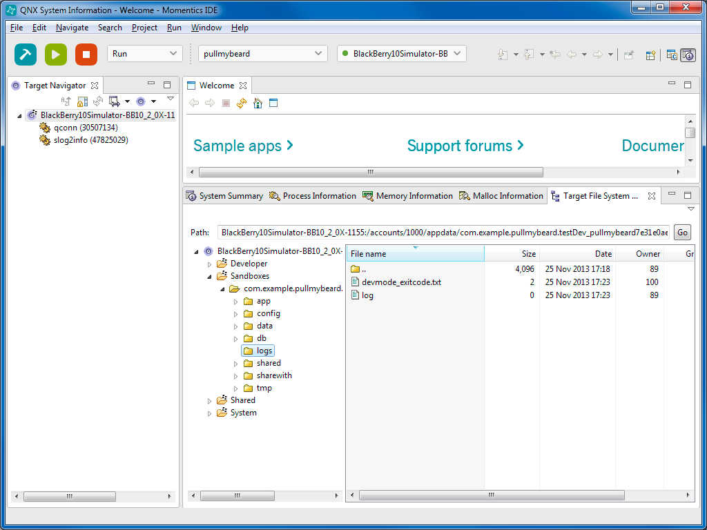

Attached Image: Figure 2 - Customize Hair.jpg
Figure 2: Each customization panel offers an assortment of thumbnail options.


The Body panel has a library of common body sizes and shapes including separate Male and Female libraries and just like the Face panel, you can blend between 2 different body thumbnails. The character view shows the whole character and not just the face and lets you rotate around the character's body. There are also menu options to switch to a view of a specific body part.
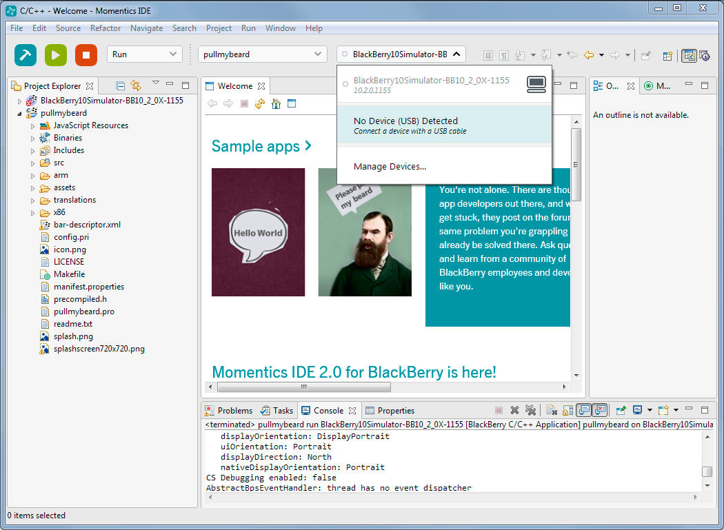
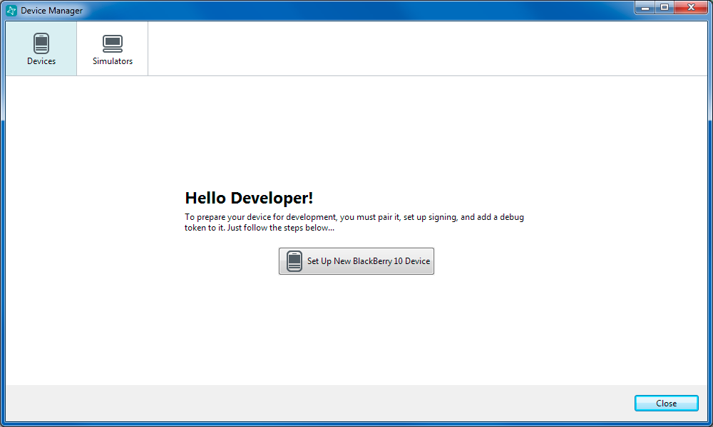
Each of the different body parts also has two thumbnails and a slider for blending between the two. Using these controls, you can create a customized look and shape for each of the different body parts. The body parts you can change include the left and right arm, upper arm and lower arm, the chest, breasts, stomach, backside, legs and feet.

The Clothes panel has separate sub-panels for selecting shirts, pants and shoes. Each sub-panel has a library of thumbnails that you can select from and the selected clothing articles automatically fit perfectly around the selected character regardless of its customization (Figure 3). Of all the libraries, the clothes libraries are by far the largest including everything from sporty styles to formal wear.


Attached Image: Figure 3 - Customize Clothes.jpg
Figure 3: Applied clothing fit the character regardless of its size and shape.


Exporting a Character


When you're finished customizing the character, simply click the Finish button and you'll be taken to a page where you can export your completed character. You will first be prompted to give the character a name. Named characters are saved as thumbnails in your Character Designs page, which is the first page you see when you sign-in. Beneath the character's thumbnail are icons to Generate Character, Edit or Delete. The Edit button returns you to the Customization panels where you can change any of the custom features.

The Generate Character button lets you export the character. There is an Options page where you can specify the Character's Height in centimeters. The default female height is 172 cm and the default male height is 183 cm. You can also set the Character Orientation to Y-up or Z-Up. For Textures, you can choose to include separate textures for the clothes and for Specular and Normal Maps. The Skeleton Resolution option lets you set the skeleton rig to use a Biped (which is a common rig for 3ds Max), or set the resolution to Medium or High.

You can also set the resolution of the character mesh to extra low (Crowd), Low, Medium and High. Several export resolutions can be selected to export together. Remember that Medium and High resolution characters are reserved for paid accounts. There is also an option to output the mesh geometry to Triangles or Quads. If you have a paid account, you can select to include Facial Blend Shapes or a Facial Bone Rig for animated facial features.

The final export option is the File Format. The available formats are Maya (.mb file) or FBX for 3ds Max and MotionBuilder. You can also select to output to both file formats at the same time. Once the options are set, all that is left is to click the Generate button and the process is done out in the cloud. Once generated, the character shows up in the Generated Characters page where it can be downloaded and saved to your local system. Downloaded files are compressed as .zip files, which includes the mesh along with its textures.

The final test is to see how the resulting character shows up in its intended package. My custom character was loaded into 3ds Max and came in without any trouble, complete with an animation rig, as shown in Figure 4.


Attached Image: Figure 4 - Exported Character in 3ds Max.jpg
Figure 4: The custom character exported out of Character Generator shows up in 3ds Max complete and ready to animate.


Summary


It is great to see that Autodesk is putting the cloud to good work. Rather than inserting these new character building features into each of its products, the new Autodesk Character Generator runs in a web browser and all the magic happens in the cloud. The most amazing part of Character Generator is in its simplicity. With just a few simple intuitive controls and little experimentation, any user can add complex, rigged, fully clothed, custom characters to their scenes. The resulting characters are absolutely amazing and look fantastic.

And don't be fooled by the simplicity of the product. With expandable libraries of body parts, shapes and styles, along with the ability to blend between them, the product offers a limitless number of possibilities. The big winner here is the game studios that can reduce character development and the creation of crowds from a couple of months to less than a day. Kudos to Autodesk.

Perspective projections in LH and RH systems

$
0
0
I have been writing an DirectX / OpenGL rendering engine recently. As you may know, DirectX is by default associated with a left-handed coordinate system (LH) and OpenGL with a right-handed system (RH). You can compare both of them in the article title image to the right. You can look at those two systems in another way. If you want to look in a positive direction, for LH, you have Y as UP axis and for RH, you have Z as UP axis. If you dont see it, rotate the RH system in the image. Today, in time of shaders and, you can use one or another in both systems, but you need to take care of few things.

I have calculated both versions of matrices for both systems. I am tired of remembering everything and/or calculating it all over again. For this reason I have created this document, where I summarize needed combinations and some tips & tricks. This is not meant to be a tutorial “How projection works” or “Where those values come from”. It is for people who are tired of looking how to convert one system to another or how to convert one API to another. Or it is for those who don't care “why” but they are happy to copy & paste of my equations (hovewer, don't blame me if there is something wrong).

RH system has become some kind of a standard in a computer graphics. However, for my personal purposes, LH system seems more logical to visualise. In my engine, I wanted to give the decision to the user. At the end, my system supports both orientations.

If we looked more closely at DirectX and OpenGL, we can see one important difference in a projection. It doesn't matter if we use LH or RH system, in DirectX projection is mapped to interval [0, 1] while in OpenGL to [-1, 1]. What does that mean? If we take the near clipping plane of a camera, it will be always mapped to 0 for DirectX, but in OpenGL it is more complicated. For LH system, near will be 1, but for RH, it will became -1 (see graphs 5 and 6 in a later section). Of course, we can use DirectX mapping in OpenGL (not the other way), but in that case, we are throwing away half of the depth buffer precision. In the following sections, we will discuss this more closely.

Personally, I think that whoever invented OpenGL depth coordinates must have had a twisted sense for humour. DirectX's solution is far better and easier to understand.

[Note]Matrix order used in this article will be row based. All operations will be done in order vector · matrix (as we can see at (1) ) with indexing from (2).</i>

Attached Image: matrix_eq1.png

Attached Image: matrix_eq2.png

For column based matrix, order of elements is reversed - matrix · vector . In a time of a fixed function pipeline, that was more problematic than today. In a time of shaders, we may use whatever system and layout we want and just change the order of operations or read values from the different positions in matrices.

World to View transformation


In every transformation pipeline, we need to first transform geometry from the world coordinates to a view (camera) space. After that, you can do a projection transformation. View matrix must use the same system as your final projection, so it must be LR or RH. This section is mentioned only for complete look up, so you know how to transform a point. There will be no additional details for view transformation.

View matrix has the same layout for both of the systems (3)

Attached Image: matrix_eq3.png

Differences are in base vectors and the last row elements calculation. You can see it in table 1.

LHRH
look|wLook - eye||eye - wLook|
right|wUp x look||wUp x look|
up|look x right||look x right|
A-dot(right,eye)dot(right,eye)
B-dot(up, eye)dot(up, eye)
C-dot(look, eye)dot(look, eye)

Table 1: View vectors calculation. wLook is camera lookAt target, eye is camera position and wUp is camera up vector - usually [0,1,0]. "x" stands for a vector product

Perspective projection


For “3D world” rendering, you will probably use a perspective projection. Most of the time (like in 90% of cases) you will need a simplified perspective matrix (with a symmetric viewing volume). Pattern for such a projection matrix can be seen at 4. As you can see, this matrix is symmetric. For column and row major matrices, this simplified pattern will be the same, but values of D and E will be transposed. Be aware of this, it can cause some headaches if you do it the other way and not notice it.

Attached Image: matrix_eq4.png (4)

Now, how projection works. We have an input data in the view space coordinates. From those we need to map them into our screen. Since our screen is 2D (even if we have so called 3D display), we need to map a point to our screen. We take a simple example:

Attached Image: matrix_eq5_6.png

where x,y,z,w is an input point ( w is a homogenous coordinate, if we want to “debug” on a paper, the best way is to choose this value as 1.0). Division by ( D · z ) is performed automatically after vertex shader stage.

From equations 5 we have coordinates of a point on 2D screen. You may see, that those values are not coordinates of pixel (like [756, 653]), but they are in a range [-1, 1] for both axis (in DirectX and also in OpenGL).

From equation 6 we have depth of pixel in range [0, 1] for DirectX and [-1, 1] for OpenGL. This value is used in depth buffer for closer / distant object recognition. Later on, we show how depth values look like.

Those +1 / -1 values, that you will obtain after projection, are known as a normalized device coordinates (NDC). They form a cube, where X and Y axis are in interval [-1, 1] for DirectX and OpenGL. Z axis is more tricky. For DirectX, you have an interval [0, 1] and for OpenGL [-1, 1] (see 2). As you can see now, NDC is a LH system, doesn't matter what input system you have chosen.

Everything, that is inside of this cube, is visible on our screen. Screen is taken as a cube face at Z = 0 (DirectX), Z = 1 (OpenGL LH) or Z = -1 (OpenGL RH). What you see on your screen is basically content of a NDC cube pressed to single plane.


Attached Image: fig2.png
Figure 2: OpenGL (Left) and DirectX (Right) NDC


We summarize computations for LH / RH system and for DirectX and OpenGL in two different tables. Those values are different for LH / RH system and of course for API used. In following sections, you can spot the differences. If you are interested where those values come from, look elsewhere (for example OpenGL matrices are explained here: Link). There are plenty of resources and it will be pointless to go over it again here.

DirectX

Attached Image: table2.png
Table 2: Projection matrix calculation for DirectX. Input parametrs are: fovY - field of view in Y direction, AR - aspect ratio of screen, n - Z-value of near clipping plane, f - Z-value of far clipping plane

Changing only values at the projection matrix won't work as expected. If we render same scene with same DirectX device settings, we end up with turned scene geometry for one of those matrices. This is caused by depth comparison in depth buffer. To change this settings is a little longer in DirectX, than for OpenGL. You need to call functions in code snippet 1 with values in table 3.

deviceContext->ClearDepthStencilView(depthStencilView, D3D11_CLEAR_DEPTH, 1.0f, 0);
....
depthStencilDesc.DepthFunc = D3D11_COMPARISON_LESS_EQUAL; 
device->CreateDepthStencilState(&depthStencilDesc,&depthStencilState); 
deviceContext->OMSetDepthStencilState(depthStencilState, 1); 
Code 1: Code snippet settings for LH DirectX rendering

LHRH
D3D11_CLEAR_DEPTH1.00.0
depthStencilDesc.DepthFuncD3D11_COMPARISON_LESS_EQUALD3D11_COMPARISON_GREATER_EQUAL

Table 3: OpenGL setting for both systems

OpenGL

Attached Image: table4.png
Table 4: Projection matrix calculation for OpenGL. Input parametrs are: fovY - field of view in Y direction, AR - aspect ratio of screen, n - Z-value of near clipping plane, f - Z-value of far clipping plane

Again, changing only values at the projection matrix won't work as expected. If we render same scene with same OpenGL device settings, we end up with turned scene geometry for one of those matrices. This is caused by depth comparison in depth buffer. We need to change two things as we see in table 5.

LHRH
glClearDepth(0)glClearDepth(1)
glDepthFunc(GL_GEQUAL)glDepthFunc(GL_LEQUAL)

Table 5: OpenGL setting for both systems

Conclusion

If you set the comparison and depth buffer clear values incorrectly, most of the time, you will end up with result like on the figure 3. Correct scene should look like on the figure 4.


Attached Image: fig3.png
Figure 3: Incorrectly set depth function and clear for current projection

Attached Image: fig4.png
Figure 4: Correctly set depth function and clear for current projection


Using equation 6, we can calculate projected depth for any input value. If we do this for values in interval [near, far], we will get the following result (see image 5 and 6). Notice second graph x-axis. For RH system, we need to change sign of near to -near in order to obtain same results as for LH system. That means in plain language, that for LH we are looking in positive Z direction and for RH we are looking in negative Z direction. In both cases, viewer is located at origin.


Attached Image: fig5.png
Figure 5: Projected depth with DirectX and OpenGL LH matrices (values used for calculation: near = 0.1, far = 1.0)

Attached Image: fig6.png
Figure 6: Projected depth with DirectX and OpenGL RH matrices (values used for calculation: near = -0.1, far = -1.0)


From above graphs, we can see that for the distances near to the camera, there is a good precision in the depth buffer. On the other hand, for larger values the precision is limited. That is not always desired.

One possible solution is to keep your near and far distances together as close as possible. There will be less problems if you use interval [0.1, 10] instead of [0.1, 100]. This is not always possible if we want to render large 3D world enviroments. This issue can be however solved as we show in the next section.

Depth precision


As mentioned before, using a classic perspective projection brings us a limited depth precision. The bigger the distance from viewer, the lower precision we have. This problem is often noticable as flickering pixels in distance.

We can partially solve this by logarithmic depth. We decrease precision for near surroundings, but we have almost linear distribution throughout the depth range. One disadvantage is that logarithm is not working for negative input. Triangles, that are partially visible and have some points behind viewer (negative Z axis), won't be calculated correctly. Shader programs usually won't crash with negative logarithm, but the result is not defined. There are two possible solutions for this problem. You either tesselate your scene to have triangles so small, that the problem won't matter, or you can write your depth in a pixel shader.

Writing depth in a pixel shader brings disadvantage with turned off depth testing for geometry before rasterizing. There could be some performance impact, but you can limit it by doing this trick only for near geometry, that could be affected. That way, you will need a condition in your shader or use different shaders based on geometry distance from viewer.

If you use this modification, be aware of one thing: The depth from vertex shader has range [-1, 1], but gl_FragDepth has range [0, 1]. It's again something OpenGL only, since DirectX has depth in [0, 1] all the time.

For a more detailed explenation, you can read an excellent article at Outtera blog (Link). Equations in their solution are using RH system (they aimed primary for OpenGL). So once again, we show same equation in LH and RH system. Both version are at table 6. This time only for OpenGL, since in DirectX problem can be solved, as proposed in article, by swapping near and far.

LHgl_Position.z = (-2.0) * log((-gl_Position.z) * C + 1.0) / log(far * C + 1.0) + 1.0
RHgl_Position.z = (2.0) * log((gl_Position.z) * C + 1.0) / log(far * C + 1.0) - 1.0

Table 6:Calculation of new Z coordinate for depth using log. C is linearized component, default value is 1.0, far is camera far plane distance, gl_Position is output value from vertex shader (in perspective projection). You MUST remember to multiply gl_Position.z by gl_Position.w before returning it from shader.

If you have read the Outtera article and looked at my equations, you may notice that I used gl_Position.z in logarithm calculations. I don't know if it is a mistake by Outtera, but with W, I have nearly same results for RH system (as if I used Z), but LH is totally messed up. Plus, W is already linearized depth (distance of point from viewer). So first visible point has W = near and last one has W = far.

If we plot classic vs logarithm depth with equations from 6, we end up with the two following graphs. Red curve is same as in previous chapter, green one is our logarithmic depth.


Attached Image: fig7.png
Figure 7: Projected depth with classic perspective and with logarithmic one in LH (values used for calculation: near = 0.1, far = 1.0, C = 1.0)

Attached Image: fig8.png
Figure 8: Projected depth with classic perspective and with logarithmic one in RH (values used for calculation: near = 0.1, far = 1.0, C = 1.0)


You can observe the effect of both projections (classic and logarithmic one) at this video (rendered with LH projection in OpenGL):


Oblique projection


Last section related to a projection will be a little different. So far, we have discussed perspective projection and precision for rendering. In this section, another important aspect will be converted to LH and RH system and to OpenGL / DirectX.

Oblique projection is not some kind of special projection, that makes everything shiny. It is classic perspective projection, only with improved clipping planes. Clipping plane for classic projection is near and far, but here we change near to get different effect. This kind of projection is mostly used for water reflection texture rendering. Of course, we can set clipping plane manually in OpenGL or in DirectX, but that won't work in a mobile version (OpenGL ES), a web version (WebGL) and in DirectX we will need a different set of shaders. Bottom line, solution with clipping plane is possible, but not as clean as oblique projection.

First we need to precompute some data. For a clipping, we need obviously a clipping plane. We need it in our current projective space coordinates. This can be achieved by transforming our plane vector with transposed inverse of the view matrix (we are assuming that the world matrix is set as identity).

Matrix4x4 tmp = Matrix4x4::Invert(viewMatrix);
tmp.Transpose();	 	
Vector4 clipPlane = Vector4::Transform(clipPlane, tmp);	

Now calculate the clip-space corner point opposite the clipping plane

float xSign = (clipPlane.X > 0) ? 1.0f : ((clipPlane.X < 0) ? -1.0f : 0.0f); 	
float ySign = (clipPlane.Y > 0) ? 1.0f : ((clipPlane.Y < 0) ? -1.0f : 0.0f);
Vector4 q = (xSign, ySign, 1, 1);

Transform q into camera space by multiplying it with the inverse of the projection matrix. For a simplified calculation, we have already used an inverted projection matrix.

DirectX

In DirectX system, we need to be careful, because original article is using OpenGL projection space with Z coordinate in range [-1, 1]. This is not possible in DirectX, so we need to change equations and recalculate them with Z in a range [0, 1].

Following solution is valid for LH system:

q.X = q.X / projection[0][0];	 	
q.Y = q.Y / projection[1][1]; 	
q.Z = 1.0f;	 	
q.W = (1.0f - projection[2][2]) / projection[3][2];

float a = q.Z / Vector4::Dot(clipPlane, q);	 	
Vector4 m3 = a * clipPlane;

OpenGL

The following equations can be simplified, if we know handness of our system. Since we want to have an universal solution, I have used a full representation, that is independent on the used sytem.

q.X = q.x / projection[0][0];	 	
q.Y = q.Y / projection[1][1];
q.Z = 1.0 / projection[2][3]; 	
q.W = (1.0 / projection[3][2]) - (projection[2][2] / (projection[2][3] * Matrix.M[3][2])); 	

float a = (2.0f * projection[2][3] * q.Z) / Vector4::Dot(clipPlane, q);	 	
Vector4 m3 = clipPlane * a; 		
m3.Z = m3.Z + 1.0f;

In calculation of m3.Z we can use directly addition of value +1.0. If we write separate equations for LH and RH system, we can see why:

LH: m3.Z = m3.Z + projection[2][3]; //([2][3] = +1) 	
RH: m3.Z = m3.Z - projection[2][3]; //([2][3] = -1) 

Final matrix composition

Final composition of the projection matrix is easy. Replace the third column with our calculated vector.

Matrix4x4 res = projection; 	
res[0][2] = m3.X;
res[1][2] = m3.Y;
res[2][2] = m3.Z;
res[3][2] = m3.W;

Attachment


I have added an Excel file with projection matrices. You can experiment for yourself by changing near and far, or any other parameters and see the differences in depth. This is the same file that I used for creation of posted graphs.

References

Path Finding for innovative games: Graph Creation and Best Path Selection

$
0
0
In the previous article, I mentioned a new approach you should consider if you want to build next-gen, innovative games, called Biological Path Finding (BPF). I always thought that the most used models are not a bible, to use without thinking about, and that doubts are often the factor that brings our mind to create better AI models.

Please note that you need to read the previous article of this topic (relative to the Navigation), before reading this one.

Graph Creation


If you want to build a single videogame per time, for a videogame similar to a lot of others, if you have few NPCs living in the same time and you don’t mind that they sometimes (or often) do what humans never do when walking, you could find the NavGrid or the NavMesh models as enough and good, without any customization. Conversely, the future of videogames can’t be built continuing to make NPCs that pretend to be humans, but rather having high credibility with new features, by adopting newer models that provide all these features without customizations.

The current Navgrid and Navmesh models have good pros, but even stronger cons. For instance, both could make, in several circumstances, long time for the off-line calculations, and both should not be used when there are several NPCs living together in a wider level. Not if you want your game go fast, and not if the correctness of the human behaviour is a must.

Moreover, the Navgrid should not be used for 3D maps for wider levels, unless you want to raise the amount of connections a lot, letting the path calculation be even more complex, with obvious performance issues.

If you think to a human with his needs, not only abstractly, logically, you find that the number of the graph nodes that has to be put into the level map is much less than with Navmesh or Navgrid, in any map and circumstances, having also a better human behaviour in the movement of NPCs.

How is this possible? The goal is taking into account only the points of the level where there is the connection between two micro-environments: next to a corridor, between two neighboring columns, a doorpost etc.

A postulation of this approach is that a micro-environment can be such if the focal points to connect it with contiguous micro-environments are all visible one each-other. So, for example, a corridor formed by two big objects, placed in the middle of a wider place, let the design-time elaboration create two focal points, each at the beginning (or ending) of the corridor. I use the same term used by Lynch (1960) about these important points, naming them as “focal points” (see the previous article for more info).

Another postulation tells this: if the micro-environment is minimal, speaking about dimensions referred to the dimension of a medium NPC (i.e. between two columns), the two focal points that will be automatically created by the graph calulation algorithm will be reduced to only one, placed in the middle of the space between them.

Focal points are the only parts of any zone that humans and animals take into consideration, in a path, when they need to change direction. Moreover, during the movement along the path, the BPF (Biological Path Finding) states that the agent will direct not toward the next focal point, but toward the last focal point, along the path, that the agent is able to “see”. This is an innovation that improve further the agent’s credibility, and this is what really humans do when are in place of agents.


Attached Image: Image1.jpg


Look at the image. The Green Circle, located in the left part of the building, is the position where the NPC is placed, while the Orange Circle is its target. The wider green line is the path that the NPC will use thanks to the BPF, while the thin green line tells the selected path. The Violet Circles, instead, sign the change of the kind of viability, and only the NPCs able to jump (at a defined height) will see them.

As you can see, the second focal point the NPC will take into consideration is not the second in the selected path, but the third, while the fourth that will be used is the seventh of the selected path. This is because of the previously mentioned rule, with whom the run-time approach of the BPF states that the NPC will not lose its “mind” in following each focal point of the chosen path, but will use, of them, only the “farthest, still visible” one. The result is that the number of focal points that will be used is only two, instead of five provided by the path of the mental map.

A solution like that will not only produce, probably, the lesser amount of focal points (or waypoints, as you wish) ever, but even will enhance the human behaviour simulation. Consider a real person in the same context of the NPC of the linked image (the building is a church). Throw away all the paths and focal points, and imagine how he behaves in that context. If he decides to follow the path that our NPC will use, he certainly goes straight forward, until the parts of the buildings will allow him to do in that way, and then will start to turn (a bit in advance, respect to the focal point) in order to go another time straight, until the building will allow him to do in that way, or until his target has been reached.

Together with these rules, the whole BPF implementation needs to have some others, that solve other use cases. It's better not to mention them as a matter of practicality and space, but you should have enough detail about them in the book I wrote and that will be published in the next weeks.

If the human doesn’t know (much) about the zone, the focal points will help him to understand it, because they are placed where he will stop and see how the next micro-environment is made (for instance, think about a dungeon with several rooms).

Coming back to the general level of this topic, we can say that the generation games and, especially, the innovative games, in the early future will have the need to have more features and better performance, without putting complexity over complexity on an AI model that does not already provide those features.

In detail, an innovative path finding model should provide:
  • A faster off-line calculation of the single graph, respect to the current ones*.
  • Ability to let the NPCs use multi-genre paths, that is letting NPCs use not only walk and run along the path, but even jump, climb, swim etc.
  • Ability to have different good paths for different species of NPC, according with the physical characteristics of each NPC species
  • A faster run-time calculation of the “plausible best path”**
  • Resolve the problem of the dynamic objects along the paths with no added complexity
  • Find multiple targets, not only of the same kind of NPCs, but even of the same species (i.e. shelters of different types)***
  • Change the graph dynamically when walls and big objects change their positions
  • Take always into consideration that the mental map of each NPC can be different from the actual map
(*) This is not a mandatory need, respect to the one of the run-time calculations.
(**) As the Psychology states (Lynch, 1960), a human is not able to: 1) remember a map as if he has the map physically on his hands, especially if the zone is not “lived” by the NPC for a while. Then only some parts of the path (the focal points) will be remembered better; 2) emotions and the need to decide fast can obfuscate the reasoning, and then the decide path can often be not the one that the logic would propose.
(***) It’s time, I reckon, that 'smart' games will adopt the natural subdivision among NPCs, in order to better use the new features of the next-gen path finding solutions and innovative decision-making systems.

Best Path Selection


District Best Path Selection

BPF is so different in respect to the classical, “only-logic” approach, that work better without any use of the current algorithms used to find the shorter path. Without entering into details, the weight of emotions, mental map errors, the NPC's species characteristics and the fact that the amount of districts in a level can’t be higher, will usually bring to have only one path that overcomes all the filters. In this context, with a single path that will be the result of the filters, the use of the algorithm to find the best path is useless and redundant.

For example, a wide level could use a total of 10 districts (see my previous article for more info). Normally, each district could have even four other districts connected to them (unless the level develops even in height). Unless the level is made by a sequence of districts, it’s rare that the target is more than two districts far from the NPC. In this case, it’s useless to adopt any kind of calculation of the best path, regarding the District level (see the previous article).

One of the simplest and effective solutions to limit paths a lot, from the human behaviour point of view, is to avoid all the paths whose first district is not far from the direct line between the NPC and its target (presuming the NPC knows, broadly, the map). Then, you should eliminate the paths containing at least one district checked as "to be avoided" for the species type of the NPC. For instance, if a district is full of dangerous monsters that can kill the NPC, or is full of micro-environments non-viable or viable with difficulty by that NPC species, or even if the path contains a darker zone and the personal traits of the NPC (if available) depict it as a non-courageous individual, the decision-making system should flag the district as "to be avoided" (or even the developer in design-time).

Another filter is the "sensation of the length" of each path. Look at this filter, because it should be difficult to implement but extremely useful, because it is one of the most used by our mind. Humans and the most intelligent animals should take into consideration the sensation of the length of a path. There can be several factors that could take place in the definition of the length sensed by a biological entity, like emotions proven during the past traversals and the fact that the path is mostly straight or tortuous.

Often, our sensation doesn't correspond to the real length of the path, and for this reason we must avoid making real calculations, unless you want to come back and have non-credible NPCs. If you want to use this filter without falling into really difficult psychological studies, you can even create two flags for any focal point, whose duty is reproduce the type of the two micro-enviroments between which the focal point is placed. The flag unchecked could mean that the mini-environment is straight, while the flag checked means that it is somewhat tortuous. The higher the amount of checked flags along the path, the lower the probability that path will be used.


Attached Image: Types of micro-environments.jpg
An example of a focal point and its two flags indicating the type of the two adjacent micro-environment.


Then, another filter is relative to the knowledge of the districts by the NPC. This is another important feature that a well-done human simulation could consider. The knowledge map of the district, made per NPC or per Species (to ease the code and the run-time system), could be made randomly or, in case of long-living NPCs, by recording the places traveled by the NPC.

Normally, the result should be one to two paths, maximum three of them. What is then the one to use, if there are more than one of them? Simple: the path containing the highest amount of districts traversed by the linecast that goes from the NPC toward the target, balanced by the less amount of districts of each path. In fact, bear in mind that humans and animals, when faced with a path finding issue, have no time to sit (imagining that an animal can do it!) and make any sort of calculation. All of them use the info gathered in the past (the other filters) and common-sense.

To recap the filters:
  • Only the district paths whose first district is not far from the direct line between the NPC and its target
  • Only paths without "to be avoided" districts
  • Sensation of the Length of the Path
  • Only paths without unknown districts
...

If the result is more than one district path:
  • Take the path with the lower number of districts or have the higher amount of district traversed by the direct line between the NPC and its target

Inner Best Path Selection

After having decided the district path to follow, the NPC has to start to resolve the path finding inside the current district. Then, when inside the next districts, redo the same for that district. The division of the level into districts (cubes) normally leads to have several cases into which two districts are linked together by more than one walkable (or better usable) surface. This means that an NPC could have more than one solution to go to the next district of the chosen district path.

Even if the division of the paths into two levels speeds up the run-time selection of the best path and forces you to split the path finding into more than one step, there are some new issues you should face with, in order to use the approach correctly. In the case of the passage between two districts, there are two things the design-time elaboration of the paths should check: the "dead paths" and the connections between passages through districts. In fact, if one of the possible paths whom connect two contiguous districts stops into the district without the possibility to pass to another one, the NPC should know previously about this issue.

In order to fulfil the problem, in design-time we shall select, for each district, the paths that travel the district by going from one contiguous district to another each contiguous to the district in question. This could be a time consuming calculation, especially if the number of the passages between contiguous districts are high. This could be a good reason to modify manually the districts, in order to avoid having too many links between two districts.

Anyway, the calculation to be done should be the following:

A - select the district


A1 - select one side of the district where there is at least one passage to the contiguous district


A11 - For each passage, check if there is a path that conduct to another contiguous district. If so, flag the passage as compatible with the passage to that district (in the way you wish).


Look at the fact that there is no need to calculate the length of each path, and this helps a bit.

The data relative to the possible passages to the next districts will be then used in run-time to check which passage to select to go to the next district. If there are more than one passages that traverse the district toward the next one, the NPC mind should decide which to use. How? You should use the same filters adopted to the district level of the path finding, but I suggest to use one or two, between the sensation length and the distance of the passage respect to the direct line toward the target.

When you have the initial part of the inner path (where the NPC is entering into the district, or where the NPC is placed) and the passage to the next district, or where the target is placed, you shall select the path to use to arrive to your next path finding goal. Even in this case, you should use the filters already discussed. It's up to you to decide which of them, or use all.

Note, though, that this way of thinking, from the NPC, is not the right way if your project is a tactical war game. The tactical war game is one of the rare situations in which the paths could be already well known by each NPC "at the table". In this case, then, a good solution remains one of the correct, only-logic approaches. The only filter you should add is the arousal level of the emotions currently lived by the NPC (arousal is, for emotions, something similar to the volume for the music). This is, though, an issue not directly managed by the PF system, even if it could change the reasoning phase of an NPC about the best path find selection.

Nonetheless, you could easily note that the Biological approach should be faster than the current ones, because the actions to be executed are lightweight, and with a reduced amount of nodes in the graph, even thanks to the division of the paths into two levels (see the first article for more info).

Conclusion


The biological approach to a path finding, inherent in the Biological Path Finding, can be used not only for humans, zombies, monsters and aliens, but even for intelligent animals and, using the right limits, with any other kind of animal.

Nonetheless, never underestimate the role of emotions under the path finding issue. Even ability to take decisions, like the one explained in this article, is a feature made not only by logic. As a confirmation of this statement, Plutchik said that emotions are basic adaptations needed by all organisms in the struggle for individual survival (1980, p. 145). He suggested that the selection occurred in the Cambrian era, 600 million years ago. The eight adaptations are incorporation, rejection, destruction, protection, reproduction, reintegration, orientation and exploration. This means, also, that the most important filters of the Mental Navigation, emotions, are shared with a wide variety of animals.

So, what differs from humans way to solve a path finding to the ones of animals? The difference is rather small, and is only related to the use of logic. This is not entirely true, but the causes of this are so profound and so difficult to be reproduced in code that I prefer not to mention it in this context.

Most animals are unable to use training to better govern their emotions, and they are also unable to take into consideration more than one deduction relative to the filters adopted. If you want to differ the human behaviour to the animal one, toward the decision for the path selection, use only one filter for the simplest animals, and then apply other filters as you are facing more intelligence animals. The only filter you should always use is the one relative to the selection of only the paths whose first focal point is toward the direction of the target.

The next article will be focused on the Mental Map, Dynamic Object Avoidance and Smoothing movements.

Article Update Log


14 Mar 2014: Title modification, moved the image as an attachment, some other changes
10 Mar 2014: Initial release
Viewing all 17825 articles
Browse latest View live


<script src="https://jsc.adskeeper.com/r/s/rssing.com.1596347.js" async> </script>