Quantcast
Channel: GameDev.net
Viewing all 17825 articles
Browse latest View live

Notes on GameDev: Tamir Nadav

$
0
0
Originally published on NotesonGameDev.net
October 22, 2008


Tamir Nadav, formerly a programmer who has marked his path out as a game designer at KingsIsle, has been involved in the industry for over 5 years with his enthusiastic networking abilities. He's always up for an interesting conversation and pitches in with events like Women In Games International, which promotes the inclusion and advancement of women in the games industry, worldwide.

You’re pretty notorious in the conference-going circles and I remember seeing you at just about every event I was at. What value do you see in attending game events?

The biggest one, of course, is networking. One minute I'm talking to an aspiring game designer, then someone like Gordon Walton walks by, and we all end up in a conversation. Since there are a huge amount of us game nerds in one place, who all have a common interest, it makes it very easy for those situations to happen to everyone.

So then, what's your favorite conference story?

Oh, wow. I'm not sure I have a favorite. The majority of good stories happen behind the scenes with other Conference Associates, and we're not supposed to talk about that! But, if I had to pick something to be shared, it would be the same story that I experience at every conference I attend, and that is the combination of the new friends I make each conference I attend, and watching the old ones continue in their career.

Speaking of careers... How did you make the career transition from programmer to designer?

Well, I started very early on in development as an Associate Programmer on an unannounced project at KingsIsle. The other two programmers were our Sr. and our Lead, shortly followed up by another Sr. There wasn't a whole lot for me to work on aside from simple prototyping, so I ended up assisting Tom a lot with design. Through a combination of them noticing that I really enjoyed design, and me not quite performing as well as I would have liked as a programmer to keep up with the other guys, and perhaps a few other factors as well, I was basically asked if I'd like to make the switch. I said sure, and here I am. :)

What drove you to you go for the "indie" life instead of working for a bigger company?

I wish I had a much better reason, but basically they were the first company who decided to hire me. :) In general, I think I'm indifferent to working for either or, because each has their ups and downs, but I can definitely say I highly enjoy my time here at KingsIsle. It's been 3 years now!

What's it like working at KingsIsle Entertainment?

We're in Austin, which sums up a lot of the culture here! I'd say that we're all rather laid back, and from what I've heard from others, don't experience many of the problems that other companies do. We don't go out and party as much as some studios, but since we're made up of many people with families or at least spouses, we've been pretty good at placing family obligations first and allowing time to spend with our loved ones. We still have the stereotypical nerf gun wars, and arguments over Kefka vs. Sephiroth, and quote Star Wars and Family Guy, and all the usual things you'd expect from a game company, though.

How much of your personality comes out in Wizard101?

Well, I'll say not very much, and a heck of a lot. I did very little work on Wizard101; most of my time has been spent working on another yet-to-be-announced project at KingsIsle. However, I did design one of the mini-games, Sorcerer Stones, and my voice is used for a few of the imps and monsters I believe. I say that a heck of a lot of my personality comes through, because many of us at KingsIsle have the same sort of whimsical attitude towards life; it's not "my" particular personality that shines, but mine matches very well to the personality reflected by the product.

Where do you want to head in the future as a game designer?

To design more games! I had a taste of what it's like to be quasi-famous when I was at Full Sail, and now I want to do that in the entire industry. I'd love to continue to develop my skills as a designer, as well as practice programming and art well enough to communicate effectively with the rest of the team, and eventually take my place in name at the sides of the other greats who have come before me, like John Romero, Will Wright, Tom Hall, Gordon Walton, and of course many others. I'm not going to list them all, those were just the first 4, so no one feel insulted, okay?

Any advice for those out there who also want to become a designer?

I always hear people say that the first advice for people who want to become a designer is "Don't become a designer!" I understand why people say that; being in design is a rough job, because we usually get blamed for everything, and everyone else thinks they can do our job. My advice would be to develop a thick shell, and learn to persevere through the hardest times. A designer's ideas can feel like mere offerings to the artists and programmers (and especially production) who seem to take delight in shredding them to pieces. This is a good thing; because what ends up being left over after a few of these processes, is a very core, solid idea that everyone is on board with. It's kind of like a saying that I heard a lot growing up; "Shoot for the Stars and you'll hit the Moon."

What You Are Worth to a Development Team

$
0
0
I would like to start off explaining a bit about this article on the whole before diving into the content of it. First I should mention that this article began its life as a journal entry of mine, my original hopes were to receive some more feedback from other game developers. Unfortunately I only received a couple of responses, one believing that my findings are completely incorrect and one that agreed with about half of this article. I want to point this out and make sure that you as the reader are aware that this article represents my conclusions as a game developer from my experiences with numerous teams on quite a few projects and from encounters and discussions I have had with others in this field. This is a biased article that is written from my view point, I attempt to take many factors into consideration but at the end of the day every team, company and project may vary.

With all of that mentioned I have also received quite a bit of interest in this article and some suggestions that I should move this over into the Game Dev article system to make it a bit more easily accessible for everyone (not just those who follow or stumble across my journal). So with that bit of an introduction, please read on. Throughout this article I hope to shed some light on how I and others like myself value the contributions of various team members and their talents.

Note:  
The Soapbox provides a platform for developers to stand up and speak their mind about the games industry. The views and opinions expressed in this article are soley those of the original author. These views and opinions do not necessarily represent those of GameDev.net.


Who the heck am I?


I'm a long-time programmer, concept designer and content writer (over 15 years of experience and growing). I have done a little bit of everything in my day: coding, artwork, modeling, animation, quest writing, game mechanic design, dialogue writing and even took a stab at composing. I have no false delusions of being some all-mighty game development god and I know that I simply do not have the adequate talent to be a quality graphical artist or musical composer. It is however important to note that as some of my words may seem to belittle what you do or contribute to a team it's not a personal attack, more so it's just what I have noticed as I have worked with teams, studios and clients throughout the course of my career. So with that, hide the women and children, brace yourself and let's get to it!

What is worth?


"Worth" in the broadest scope means value, so what we are discussing here is what is your "value" to the team. However it's not quite that simple; worth in the gaming industry is further broken down into sub sets that vary quite a bit (almost polar opposites as we will come to find out). There is what we will refer to as intellectual worth (or your level of contribution / importance to the game being what it is) and the other we will refer to as financial worth being how much money the team may consider you to worth. Lets go ahead and dive into these a bit more in-depth just to understand what I am talking about with these two sub sets of "worth".

Intellectual Worth


As I touched on above what I consider to be "intellectual worth" is your level of contribution to the project, quality of work and effect on the game as a whole. This is something we will expand on as we go here, it's just important to realize that what I am trying to say by this is how important are you to the game getting completed. A higher intellectual worth to me means that the game is much less likely to be completed without you! Basically the more intellectual worth you have the more critical you (or your role) is to the team, they probably don't want to lose you (until we contradict this statement later on).

Financial Worth


This is not to be confused with the idea of how much money you have, that is not the financial worth that I am speaking of here (and actually we will briefly discuss monetary contributions as intellectual worth later on). Your financial worth is how much the team thinks you should be paid for your services, be it a percentage of profit sharing, a one time project contract or an hourly rate through the course of the project itself. Unfortunately I won't be giving any concrete numbers, but I will try to give percentage-based ideas of how teams may think and or approach this topic.

Studios and Teams


These are two more terms you will find me using quite a bit as we go and I think it might be wise to define what I mean by these terms. In short, when I say "studio" in this article I am referring to an established group of developers with financial backing (funding). This would be a group of developers that may work on projects and sell them (I mean actually complete, publish and sell their games) and may or may not hire outside help as they go.

When I say "Teams" in this article I am speaking of groups of developers (normally smaller groups) that either have not yet completed and published a game title or if they have completed it they have not actually sold it or monetized it in anyway. As such we are going to assume that a "team" is a group of developers that do not have money now, they will not pay you right now. They may however have plans to get funding, donations, promissory purchase funds (kick starter) or the intention to sell the game and split the profits.

An important thing I must stress here is that I am talking about people who are trying to not only build and complete a game but people that are looking to monetize said game by some means in the near future. This monetizing means that they will sell the game to players, sell it to another studio, charge micro transactions, subscriptions, DLC, or whatever, by some means they are trying to make money. This article does not reflect the importance or worth of individuals in hobbyist projects, eg projects that are "just for fun" or "portfolio value" or by whatever means not intended to make money. Groups and developers that create not for profit games gauge worth and value totally different and there's really no way to make an assumption as to a basic guideline for them, each group will be different in this aspect. If you are part of a group working on a not for profit game I'm sorry to have wasted your time but this article is not for you.

Give me some information already!


I'm sure many people have thought this by now (maybe even literally said it to the monitor), and yes now that I have clarified what I am trying to talk about and what the various terms that I will use mean we can actually start talking about something! As this topic is a bit broad and very dependent on grouping and project's we are a bit forced to divide the conversation into multiple parts here. First off I'd like to start with teams (remember, no money right now and probably no previous works). So here's the way that I see it and what I have experienced quite a few times throughout my career...

Brain-Bulb.jpg

Teams - Intellectual Worth


Teams normally tend to measure your intellectual worth based on content contribution and quality alone. This simply means that the more you provide and the better quality you provide the more your worth. It's normally pretty cut and dry and everyone is pretty much on the same page for this one.

Programmers

It doesn't matter how technically advanced or difficult what you are doing is your team doesn't realize that. They care about the performance of your code and how fast you got it done.

Artists

It doesn't matter if you're doing pixel art, vector art or modelling it's the end result your team will judge you on. Your team doesn't realize how difficult it is to actually draw or model quality pieces they simply judge you based on how good it looks when you're done and how fast you got it to them.

Idea guys

In a small team your intellectual worth is held in pretty high regard. That is to say that the rest of the team realizes that you are the focal point of the project, without you they wouldn't be making a game they would just be making things. Your intellectual worth is normally judged on how well planned your design document is and how fast can you produce it.

Content Writers

You are the people who write the story, history, dialogue, descriptions and anything else textual or spoken within the game. You're pretty darn important to a team as you add the content that drives their graphics, mechanics and code. They make the flash to bring the player in to the game YOU write the content to keep them in the game and maybe even push them to buy it. You are important and your team will most likely judge your worth based on if you are using the correct spelling and grammar for the language you are writing, if what you write is compelling and interesting and again how fast can you get it to them?

Composers

Unfortunately your worth is judged a little more harshly than the others on the team. In many small teams music and audio effects are little more than background noise, or so they will think. Some teams will understand that you are just as important as content writers or artists in that your music is an added effect that immerses the player deeper in to the game play and helps to hook them to the game (possibly driving sales). Your worth may get judged a little more harshly here but it will still be based on how compelling are your scores, would someone actually listen to it outside of the game and yet again, how fast you get it to them.

Marketing / Advertising

This portion of game development unfortunately is completely off the radar of most small teams. As far as they are concerned you most likely aren't worth anything to them (until they realize they're not actually getting sales). If and when a team realizes that they need to advertise and market their game you become worthy and your worth is rated in a very black and white judgement. How many copies have you helped us to sell? The team is not likely to understand impressions, traffic flow, turn over rates, so forth and so on. You should really make a big attempt to educate your team to your importance and do this using facts. Spill the beans a little bit and tell them what the tricks are, although they may start to have an idea that targeted marketing is a means of getting impressions from potential buyers and even that doing this means to find communities and sites that would potentially buy their game and post advertisements to it doesn't mean they can do it as good as you can. Don't be so secretive and you're likely to be deemed a little more worthy / valuable from an intellectual stand point.

Anyone I'm forgetting

Although I may not have mentioned you directly by some means you should fit into one or more of the categories above. Please try to relate yourself as closely as you can to what I have listed and chances are your worth will be judged accordingly. Example: voice actors you are basically composers in the eyes of a team in that you are creating audio that they will use. You may or may not also be considered something of a content writer depending on your ad libbing, the more you take a simple sentence and turn it into something more interesting the more you fall into both categories. Animators, the team considers you an artist and perhaps something of an idea guy if you also extend upon the requested animations and or present your own concepts of movement. Like voice actors the more you do outside of what you are asked to the more you fit into multiple categories.

Recap

Everyone in a team intellectually starts pretty equal and your intellectual worth is almost entirely judged on doing your job. You want your team to consider you as a major part of the game? You want to be listed as a chief or a lead member? You want the game to be "You and so and so's game"? Do more and do it right. Sometimes you will make sacrifices in the interest of completing contributions and that is to be expected but if the only way you can get something done is to do it with poor quality you may very well be in the wrong field. On the same note you may make the highest quality assets ever made by someone in your position but if it takes you forever to get it done, you might be in the wrong field. Teams don't have massive amounts of money to support long term projects - know this, own this, love this, and most importantly understand that your team needs you to git 'r done so to speak.

Studios - Intellectual Worth


This one is probably going to get discouraging for lots of people because experienced development studios tend to judge intellectual worth more so on availability, quality, quantity and speed. It will sound a bit like I'm saying that a studio expects you to be a master of your art and honestly, yes they do. Experienced studios have released projects before, they have gone through the entire process and they understand who contributing what created how much of a difference to the end result. They are comparing your worth to experiences of past projects and what they feel helped or hurt said projects.

Programmers

You are held to a much higher regard by many studios (this isn't just me saying it because this is my core profession this is true in many cases). We will see this same trend coming out through this section, to put it simply an experienced team understands how important it is to have good high quality code, written fast and completed. While teams may think coders are a dime a dozen, studios tend to understand that a true programmer is hard to find. Someone that actually gets it done quickly and efficiently is worth quite a bit to a studio and you are very important to the project getting completed in their eyes.

Artists

Just like programmers studios hold you up onto your pedestal. You are VERY important, just as much as the programmer, maybe (but not necessarily) even more so. Reason being? Tons of "artists" can draw a great picture, very few can do it again and do it on command. Studios tend to understand the importance of having an artist that not only can create quality work but can do it when they are told and don't take forever to complete it. To a team you might be considered one of these dime a dozen members because there are so many self proclaimed artists out there, to a studio they have seen that a "drawer" and an "artist" are different things. A true artist is hard to find and is worth a lot to the game getting complete.

Idea guys

This one is going to sting really bad and probably cause some angry responses later on but the studio doesn't consider you worth very much if at all. I'm sorry to say it but everyone in the world is an idea guy, I have an idea for a game, you have an idea, the janitor has an idea, your girlfriend has an idea. While teams will consider you much more valuable because you truly are the keystone of the project, studios realize that any and everyone is ready to take up this role. As such you are actually in 0 demand which to the experienced studio means you're not important to the game (because it's very easy to replace you). Again I apologize that this sounds harsh but it's a reality you would do well to accept and use this discouragement as a stepping stone to learn another talent and increase your worth to the team. If you have ideas and a high school level education you should find it pretty easy to also be a content writer, maybe you can sketch out some concept designs for levels and characters and what not. All be it without the latent artistic talents (that few of us have) you probably won't make anything the team can use graphically, but being that you can at least present something graphical to further the teams understandings of your ideas and concepts (no matter how poor) you are worth a little more than the average idea guy. For further reading on why I and so many others come to this conclusion please see Game Idea Value.

Content Writers

Get ready I'm going to anger you too. Unfortunately this is another field that experienced studios hold in a low regard as to intellectual worth. Simply put they know that good old fashioned fun game play can trump a story line if need be. The idea guy can provide enough of a story outline to muscle through and they can get artists / coders to do a little more to pull the gamer's attention away from the story line of the game (or lack there of). Also, there are many good writers out there, there are a lot that will do it just for recognition or to get their stories heard. Unfortunately in the eyes of an experienced studio this makes you expendable as you can be replaced or even cut from the project and there are alternatives that the team can look into. Just like the idea guy you can learn some basic design practices, maybe provide some sketches or possibly even learn to do marketing and advertising research.

Composers

Finally you start to get some more recognition here. Experienced studios tend to realize that the audio of the game is actually much more than simple background noise. They have most likely come to realize that audio assets can be used in conjunction with mechanics and graphics to immerse the player deeper into the game and provide an overall better experience to their player. Unlike a less-experienced team the studio will more likely understand your contribution is a silent killer of sorts (ha funny I call it silent when it's music huh?). The clank of a sword, the swoosh of the bat, that subliminal feeling you get from hearing creepy music when zombies are around. These things greatly increase game play and the studio is likely to know this.

Marketing and Advertising

Your intellectual worth still isn't very high to a studio as you don't actually make a big difference to the game getting created but you will at least have some value if you provide incite and suggestions through the entire project. If you are performing research and finding what players want, relaying that to the team and helping the design target potential customers better you do have some intellectual worth to the studio.

Anyone I'm forgetting

Just like with teams, apply your skill sets to the above categories as best you can. We can always debate what "category" of contribution your specific role in the team is but most if not all times they still all break down from one of these broad overall categories. No matter what you do somehow you should fit within one or more of the above listings.

Recap

We see a bit of a shift in intellectual worth here. Studios as mentioned have experience creating games and they see people's contributions in a totally different light. As incorrect or blind as it may sound many studios tend to think this way. Being that they may have failed quite a few times before they actually succeeded they tend to be more interested in getting this project done. Bad experiences / wasted time, funds or assets from previous projects effect how they will look at you. Never ever argue with the studio management about how important you are to them, find out what they want you to do for them to consider you more important. Studios are paying you to get it done, don't tell them how they should do it, do what they ask of you and more whenever possible. This is what makes them consider you more valuable.

What-is-it-worth.jpg

Teams - Financial Worth


I have covered quite a bit in the previous intellectual worth so here in this section I'm just going to simplify things and focus mainly on how teams may consider / judge how much money they are willing to pay you based on what you do. I would like to stress once again that these are my personal experiences while working with various teams on numerous projects, this is not what I think things should be like, I'm not trying to justify or argue it, these are just the trends I have seen throughout my career. It is my opinion that this is what you will encounter when you first start working with small teams however it can and will vary from team to team.

Programmers

Here it comes guys this is the one that is a stinger to us. We're not worth much at all to teams. We all know that there are dozens of self proclaimed "programmers" out there no more than a few minutes away (to get in touch with). We're all vocal quite a bit and teams have seen so many of us around forums and job sourcing sites that simply put we're a dime a dozen. They don't want to pay you at all, they think anyone can do what you do, when they do offer profit sharing or hourly pay it tends to be insulting at best. I suggest however that if you are not getting offers from studios you suck it up and do it anyway. Studios will become more likely to consider you later on when you have worked with a few teams plus hey you'll get real experience and become a better programmer for it. If you don't always want to be a better programmer or don't see the value in getting ripped off on your first few projects you may be in the wrong field, go make websites or something. (Look I'm nearly insulting my own kind!)

Artists

This one stings a bit as well - you're just like a coder. Any of us can go to deviantArt and see hundreds if not thousands of good to high quality works and quite simply the team figures there are so many good starving artists out there they must be cheap. When you request something that seems reasonable to you they are likely to show you the door. Why would they pay you so much money when the guy on deviantArt does the same quality for $5? Granted you and I know it's never that simple. You may actually get the work done to a good quality and in a quick manner but still, teams aren't experienced they don't realize that makes a difference. It's just art and kinder gardeners can draw with crayons - just because you're a bit better doesn't mean they think you're worth more money. Just like above with the programmers though, I would suggest that you also suck it up and get ripped off a few times. Studios are more likely to hire you for what you're worth if and only if they see that you have done as you were asked in a timely manner and worked on a released project. Also, some money is better than no money isn't it? Is art not your passion? If you don't like to create art and get better / faster at it all the time perhaps you are in the wrong field and should just stick to your doodle pad. (Sorry, I insulted the programmers too. It's harsh but meant in good faith).

Idea guys

You are probably the leader of the team. You're the guy that sketched out a design document, recruited help and are driving the project. I say this because no project starts without an idea. If the Programmer starts up the idea and goes looking for help you're not likely who he will be looking for, likewise an artist with an idea is the idea guy himself and most likely doesn't need you or at least doesn't want to pay you for what he is doing and or started. With that said you normally set your own financial worth in these situations but you should be aware of the impact this will have on your team. Keep in mind everyone else on your team has an idea as well, what you are doing is nothing special to them. They may have joined you because you had the artist already and the coder is looking to make some money, or the artist might join you because you have a programmer already working on something and the artist wants to make some money. Content writers might just join you because they like the idea, they may or may not want money that's between you. For Programmers, Artists, Composers, Marketers and Advertisers however they have spent money and time in their life to learn what they are providing you. They deserve fair compensation and will quickly lose interest if you value yourself much higher than a small fraction. Again they can come up with an idea too, why are they doing all the high end work while you collect massive amounts and they get next to nothing? (Yeah I'm trending again, insulting everyone a little bit to be fair to all).

Content Writers

Your financial worth is entirely judged by the scope and depth of the project. Basically you're going to be worth what the project sets you up to be worth. That is to say that a larger RPG with heavy story line as the main selling factor is going to be a project that will pay you a little more than something that is like a platformer with a story. Just like with Programmers and Artists I suggest that you go ahead and let your self get ripped off a couple times as well. If nothing else you are perfecting your writing skills while actually publishing some work. Making a little money rather than nothing and building portfolio to move into more literary fields in the future. If you don't like to write stories and such or you think writing is only worth doing when you're making good money... Yeah you're in the wrong field. Go look around and see what short stories are worth to magazines, news papers and web sites. Go see if you can get your book published, but get out of game development. (I feel like such a bad guy talking so much smack)

Composers

Unfortunately you're in that boat with Programmers and Artists, maybe even more so. Musical composers are everywhere in this world and there are quite a few that just want to be heard. Going hand in hand with the intellectual worth misunderstanding teams pretty much figure they can get stock sound effects for free off the internet, make them work and that your music is little more than background noise, as such it's not really important. As long as it's not horrible and it's there it's good enough. I still suggest you go ahead and get ripped off a few times though. Portfolio, experience and proof that you can compose on command is worth quite a bit to a studio who may pay you fairly or even well. However since I'm bashing everyone down a notch in this section here's yours too - If you don't like to make music just to hear it and or be heard you're in the wrong field. Your music is an artistic representation of your spirit and soul, it's something you want to share with the world. If it is unacceptable that you create works for anything less than a small fortune then by all means go record an album and see if you can sell it, but game development is not for you.

Marketing and Advertising

You guys are really getting the short end of the stick through all of this. Inexperienced teams normally don't realize that just because you make the best game in the world doesn't mean you sell it and your worth is severely underrated. They figure "I'll just post on Steam and it'll sell!" or "I have a website it'll sell". More often than not the team does not realize that they have to actually get quality traffic to the sales page to make a sale. They figure they'll just post on some random forums or blast out some emails and boom - 100,000 hits over night! Partially true but how many of those 100,000 are actually looking to buy a game in your genre at your quality level for the same platform? Anyway, you guys know what I mean here that was just a bit for the non marketing savy people to understand what I'm talking to you about. With that said I have to by some means knock you guys down a peg as well, it's only fair everyone else is taking it, hopefully in stride. Although what you're doing actually translates the product into money you're actually doing the least quantity of work on the team. Yes you are highly specialized and you get results just like the professional coder or the amazing artist or the concert quality composer but... They all spent hundreds if not thousands of hours creating their contributions. You will be providing at best a few dozen hours. For amount of time invested to what you should receive you have to take a step back and understand they are not willing to give up what they have worked so hard for in order for you to chime in 6 hours of advertising. My suggestion to you is that you try to work out a per piece commission, if you're as good as you say you are this allows you to make money at your pace. If it's a low percent of each sale the team is likely to play along and if you move thousands of units you can make quite a bit of money without forcing the other members to feel like you don't deserve it.

Studios - Financial Worth


I skipped the who I forgot and recap on that last section because I went much longer than I expected per role. Hopefully this final section will run pretty quick as we have pretty much everything covered already. I'm going to try to get straight to the point here and not offer as much of the "blab" that has increased the previous sections, I assume by now your seeing the trends of thinking and I don't have to explain why the studio will feel the way they might as much.

Programmers

Aha finally we're worth some money! This will be argued by non programmers or programmers who have never worked with or been contracted by a studio but it's fact. When a studio hires or contracts you it's because you have earned that position. They expect nothing but the best from you but they're going to pay you very well to do it. Seriously, there is a TON of money to be made when you get good enough to work for a studio.

Artists

Come on guys, you're with us programmers! Many of my programming colleagues may argue this fact as you would argue the financial worth of the programmer but the fact is studios know that a talented and highly productive artist is worth gold. Just like with us coders the studio expects the world from you but they will give you the world in return for your services. Just one project done with a studio will make up for at least 2 or 3 projects you got ripped off on working with teams. Seriously, you're going to be rich.

Idea guys

I'm sorry you're not going to make a penny. Ok that might be a little rough, they might buy you a cheese burger. I'm sorry to be so blatantly rude about this but you have to understand they are spending tons of money on Programmers, Artists and other members, these other members are SO excited to not only be doing what they love but to be getting rich in the process that their brains are overloading with ideas. They are all happy to propose 10 new ideas right now for free because they are making their money doing other things. No matter how golden your idea is they're not likely to steal it nor are they likely to pay for it. At best you may get a "That's a great idea when we catch up the 40 game ideas we have we'll get back to you". If you want to work for a studio you HAVE to learn a talent they need, not try to push something on them that they have an abundance of. (Never sell salt water on the ocean so to speak).

Content Writers

You vary quite a bit and you will be looking for a large studio in order to make some money. Much like the idea guys the existing members are willing to step up and adopt your talent to get the project rolling and keep their studio running so they keep making their massive pay checks. You would be amazed how motivated these other studio employees are being that they are bringing home thousands per week or more. You will need to have quite a bit of portfolio value to get on the radar of huge story-oriented development studios that actually need dedicated writers. I'm sorry if it sounds rude but you're going to have to suffer through a lot more of the team rip offs to get noticed.

Composers

Come jump around in the happy house with us programmers and artists. Finally your talents are highly revered and you will be making very good money to be doing what you love. The studio knows your contributions add to the profit they will make and as such they are willing to pay you very well to do what you do. Just like us however you are expected and demanded to make top notch audio on command. You will be working hard but you will also be retiring early in life.

Marketers and Advertisers

Yeah you know you're making money too. The studio has sold games before they know that you have to get quality faces looking at the product to sell it and they know a large investment to you will return higher profits for them. Many times you are not hired by the studio itself as much as you are contracted, or outside advertising agencies are hired. However mid sized to large studios would rather just payroll you and have you on hand to keep it up all year round. Get good at it, and be able to prove that you will make them money and you'll be rolling in your cut as well. Just like the rest of us you will be busting your hump but the pay off will be worth it. You may however also get stuck in the rut where you will need to get ripped off quite a bit to demonstrate your ability to a level where the studio will want you but in the long run it will be worth it I promise.

In closing


As a bit of a final recap I'd like to touch on the trends that you may have noticed throughout this article. The most important of these trends, and the biggest one I hope to have presented is get it done! Whatever it is that you are doing for your project getting it done helps everyone. Game development is tightly linked through all of the fields and any one spoke of the wheel taking too long impacts overall progress ten fold. I completely understand that quality in any field takes time but we all need to understand that when that time is applied is up to us. For your project's sake wake early and bed late, spend time every day working on what you do and get it done in as few days as possible even if it costs you a night out or causes you to miss an episode of your favorite TV show.

Secondly, understand that you may not understand how hard someone else's work is. This is most noteable between programmers and artists. As programmers we tend to look at artists and think they are sitting on the couch doodling and getting paid for it. Artists tend to look at programmers and think we simply type out commands at the keyboard. What we as programmers need to understand better is that artists actually do a lot more than just doodle, they manipulate colors, lines and visual effects to make mini master pieces in a way that we can't. Artists, you need to understand that programming is in itself an art. Yes we type commands, but how you use those commands, when and where is an artwork in and of itself. Our brains work much in the same way, what we produce just comes out differently. Although I can't make such direct comparisons to all fields, at the end of the day it all comes down to the same things. We are all creative upstairs and we all create something amazing, in the case of an artist it's nice to look at but hard to understand what went into it. With programming code it's fun and easy to use or play but hard to understand what went into it. With a story line it's compelling and interesting to read but hard to understand what went into it. With audio tracks and sound effects it's pleasing to listen to but hard to understand what went into it. The trend to note: more work goes into quality works than what meets the eye, the mouse or the ear.

Lastly, development is driven by content creation and functionality. In order to make it farther, make more money and be worth more to any team or studio you have to do more. We all need to take a step back and honestly ask ourselves if what we want to provide will create a big enough impact to justify our position in a project. For programmers this may mean that your education never stops and that you must learn to specialize in all aspects of game programming. For artist this may mean you need to learn to create scenery, characters, effects, vehicles and more. For composers, you might need to expand your ability into multiple genres and learn to make more impressive sound effects. For writers and idea guys, you may need to learn to design more and better as well as learn some other things that you can do to help the game succeed (be it advertising and marketing, quality testing and assurance, quest writing, dialog, story line...). In short if you EVER have to say "yeah but I don't do ...", you are not done growing as a developer. Granted it's very difficult if not impossible to be the best at everything related to your field you should NEVER be completely unable to produce something that is within the demands of your field. On the same note, when you are to the point that you can or can't learn to do anything that your field will require it's time to start minoring in a second field.

So hopefully this will give you a little understanding of what you might encounter throughout your career as a game developer and help to prepare you for what you may encounter. To anyone who I may have discouraged throughout this article I apologize. I would hope that even throughout some of the darker points of this article that it has offered up some ideas of other ways increase your worth, or at the least opened your eyes that you can increase your worth through learning more and taking on more roles.


GameDev.net Soapbox logo design by Mark "Prinz Eugn" Simpson

Dynamic 2D Soft Shadows

$
0
0
The aim of this document is to describe an accurate method of generating soft shadows in a 2D environment. The shadows are created on the fly via geometry as opposed to traditional 2D shadow methods, which typically use shadow sprites or other image based methods. This method takes advantage of several features available in the core OpenGL API, but is by no means restricted to this platform. Direct3D would also be a suitable rendering API, and the concepts and reasoning behind the various rendering stages should hopefully be clear enough that a reader can make the conversion without too much hassle.

Note:  
This article was originally published to GameDev.net back in 2004. It was revised by the original author in 2008 and published in the book Advanced Game Programming: A GameDev.net Collection, which is one of 4 books collecting both popular GameDev.net articls and new original content in print format.


Overview


We will start by defining a few terms that we will use frequently, and a brief explanation of the phenomena that we are attempting to reproduce on our digital canvas.


Attached Image: 01Overview.gif
Image 1: Overview of terms


Light source


An obvious place to start – in this implementation we will discuss a point light source, although extending the method to include directional lights as well would be easily done, as is adding ambient lighting into the system. We use a point light source with a user-defined radius to generate the soft shadows accurately.

Shadow caster


A shadow caster is any object that blocks the light emitted from the source. In this article we present implementation details for using convex hulls as shadow casters. Convex hulls have several useful properties, and provide a flexible primitive from which to construct more complex objects. Details of the hulls are discussed in just a bit.

Light range


In reality light intensity over a distance is subject to the inverse square relationship, and so can never really reach zero. In games however linear light fall off often looks as good or better depending on the circumstances. The image above a linear fall off in the intensity is used, dropping to zero at the edge of the light range.

Umbra


The umbra region of a shadow is the area completely hidden from the light source, and as such is a single colour (the image above shows the umbra region in black since there is no other light source to illuminate this region).

Penumbra


The penumbra region of a shadow is what creates the soft edges. This is cast in any area that is partially hidden from the light but neither in full view or totally hidden. The size and shape of the penumbra region is related to the lights position and physical size (not its range).

Core Classes


First we'll have a look at a couple of classes that are at the core of the system – the Light and ConvexHull classes.

Light: The light class is fairly self-explanatory, holding all the information needed to represent a light source in our world.

Contains:
  • Position and depth. Fairly obvious, these are the location in the world. Although the system is 2d, we still use a depth for correctly defining which objects to draw in front of which others. Since we'll be using 3D hardware to get nice fast rendering we'll take advantage of the depth buffer for this.
  • Physical size and range. Both stored as a simple radial distance, these control how the light influences its surroundings.
  • Colour and intensity. Lights have a colour value stored in the standard RGB form, and an intensity value which is the intensity at the centre of the light.
ConvexHull: The convex hull is our primitive shape from which we will construct our world. By using these primitives we are able to construct more complex geometry.

Contains:
  • List of points. A simple list is maintained of all the points that make up the edges of the hull. This is calculated from a collection of points and the gift-wrapping algorithm is used to discard unneeded points. The gift-wrapping method is useful since the output geometry typically has a low number of edges. You may want to look into the QuickHull method as an alternative.
  • Depth. As for the light, a single depth value is used for proper display of overlapping objects.
  • Shadow depth offset. The importance of this is described later.
  • Centre position. The centre of the hull is approximated by averaging all the points on the edge of the hull. While not an exact geometric centre it is close enough for our needs.
  • Vertex data. Other data associated with the vertex positions. Currently only per-vertex colours but texture cords could be added without requiring any major changes.

Rendering Overview


The basic rendering process for a single frame looks like:

  1. Clear screen, initialise camera matrix
  2. Fill z buffer with all visible objects.
  3. For every light:
    1. Clear alpha buffer
    2. Load alpha buffer with light intensity
    3. Mask away shadow regions with shadow geometry
    4. Render geometry with full detail (colours, textures etc.) modulated by the light intensity.

The essential point from the above is that a rendering pass is performed for every visible light, during which the alpha buffer is used to accumulate the lights intensity. Once the final intensity values for the light have been created in the alpha buffer, we render all the geometry modulated by the values in the alpha buffer.

Simple Light Attenuation


First we'll set up the foundation for the lighting – converting the above pseudo code into actual code but without the shadow generation for now.

public void render(Scene scene, GLDrawable canvas)
{
  GL gl = canvas.getGL();
  gl.glDepthMask(true);
  gl.glClearDepth(1f);
  gl.glClearColor(0.0f, 0.0f, 0.0f, 0.0f);
  gl.glClear(GL.GL_COLOR_BUFFER_BIT |
             GL.GL_DEPTH_BUFFER_BIT |
             GL.GL_STENCIL_BUFFER_BIT);
  gl.glMatrixMode(GL.GL_PROJECTION);
  gl.glLoadIdentity();
  gl.glMatrixMode(GL.GL_MODELVIEW);
  gl.glLoadIdentity();
  gl.glMatrixMode(GL.GL_TEXTURE);
  gl.glLoadIdentity();
  gl.glDisable(GL.GL_CULL_FACE);
  findVisibleLights(scene);
  Camera activeCamera = scene.getActiveCamera();
  activeCamera.preRender(canvas);
  {
    // First we need to fill the z-buffer
    findVisibleObjects(scene, null);
    fillZBuffer(canvas);
    // For every light
    for (int lightIndex=0; lightIndex<visibleLights.size(); lightIndex++)
    {
      Light currentLight = (Light)visibleLights.get(lightIndex);
      // Clear current alpha
      clearFramebufferAlpha(scene, currentLight, canvas);
      // Load new alpha
      writeFramebufferAlpha(currentLight, canvas);
      // Mask off shadow regions
      mergeShadowHulls(scene, currentLight, canvas);
      // Draw geometry pass
      drawGeometryPass(currentLight, canvas);
    }
    // Emmissive / self illumination pass
    // ..
    // Wireframe editor handles
    drawEditControls(canvas);
  }
  activeCamera.postRender(canvas);
}

Note that code here is written in Java, using the Jogl set of bindings to OpenGL. For C++ programmers you simply have to remember that primitives such as int, float, boolean etc. are always passed by value, and objects are always passed by reference. OpenGL commands and enumerations are scoped to a GL object, which leads to the slightly extended notation from the straight C style.

First we reset the GL state ready for the next frame, collect all the lights that we will need to render this frame and retrieve the currently active camera from the scene. Camera.preRender() and .postRender() are used to set the modelview and projection matrices to that needed for the view position.

Once this initialisation is complete we need to fill the z-buffer for the whole scene. Although not discussed here, this would be the perfect place to take advantage of your favourite type of spatial tree. A quad-tree or AABB-tree would make a good choice for inclusion within the scene, and would be used for all testing of objects against the view frustum. To fill the depth buffer we simply enable z-buffer reading and writing, but with colour writing disabled to leave the colour buffer untouched. This creates a perfect depth buffer for us to use and stops later stages blending pixels hidden from view. It is worth noting that by enabling colour writing an ambient lighting pass can be added here to do both jobs at the same time. From this point onwards we can disable depth writing as it no longer needs to be updated.

Now we perform a rendering pass for every light.

First the alpha buffer is cleared in preparation for its use. This is simply a full screen quad drawn without blending, depth testing or colour writing to reset the alpha channel in the framebuffer to 0f. Since we don't want to disturb the current camera matrices that have been set up, we create this quad by using the current camera position to determine the quads coordinates.

Next we need to load the lights intensity into the alpha buffer. This does not need any blending, but depth testing is enabled this time to allow lights to be restricted to illuminating only the objects beneath them. Again colour writing is left disabled since we are not ready to render any visible geometry yet. The following function is used to create the geometry for a single light:

public void renderLightAlpha(float intensity, GLDrawable canvas)
{
  assert (intensity > 0f && intensity <= 1f);
  GL gl = canvas.getGL();
  int numSubdivisions = 32;
  gl.glBegin(GL.GL_TRIANGLE_FAN);
  {
    gl.glColor4f(0f, 0f, 0f, intensity);
    gl.glVertex3f(center.x, center.y, depth);
    // Set edge colour for rest of shape
    gl.glColor4f(0f, 0f, 0f, 0f);
    for (float angle=0; angle<=Math.PI*2;
         angle+=((Math.PI*2)/numSubdivisions) )
    {
      gl.glVertex3f( radius*(float)Math.cos(angle) + center.x,
                     radius*(float)Math.sin(angle) + center.y, depth); 
    }
    gl.glVertex3f(center.x+radius, center.y, depth);
  }
  gl.glEnd();
}

What happens is we create a triangle fan rooted at the centre position of the light, then loop around in a circle creating additional vertices as we go. The alpha value of the centre point is our light intensity, fading linearly to zero on the edges of the circle. This creates the smooth light fall off seen in the first image. If other methods of light attenuation are needed, they can be generated here. An interesting alternative would be to use an alpha texture instead of vertex colours; a 1D texture could happily represent a non-linear set of light intensities. Other unusual effects could be achieved by animating the texture coordinates over a 2D texture, such as flickering candlelight or a pulsing light source.

So now we have our light intensity values in the alpha buffer, we will skip the generation of shadow hulls for the moment and move on to getting our level geometry up on the screen.

The geometry pass is where we really start to see things coming together, using the results we have carefully composed in the alpha of the framebuffer. First we need to make sure we have depth testing enabled (using less-than-or-equals as before), and then enable and set up our blending equation correctly.

  gl.glEnable(GL.GL_BLEND);
  gl.glBlendFunc(GL.GL_DST_ALPHA, GL.GL_ONE);

Simple, yes? What we're doing here is multiplying our incoming fragments (from the geometry we're about to draw) by the alpha values already sitting in the framebuffer. This means any alpha values of 1 will now be drawn at full intensity, and values of 0 being unchanged. This is then added to the current framebuffer colour multiplied by one. This addition to the existing colour means we slowly accumulate our results from previous passes. With our blend equation set up, we simply render our geometry as normal, using whatever vertex colours and textures that takes our fancy.

If you take another look at our render() function near the top, you'll see we've almost finished composing our frame. Once we've looped over all the lights we've practically finished, but we'll insert a couple of extra stages. First an emissive or self illumination pass – this is discussed near the end of the article. After this is a simple wireframe rendering with draws object outlines such as seen in the first image.


Attached Image: 02BasicPP.gif
Image 2: Per pixel lighting with intensities accumulated in the alpha buffer.


Coloured Lighting


What was once seen as 'the next big thing' in the Quake 2 and Unreal era, coloured lighting is pretty much standard by now, and a powerful tool for level designers to add atmosphere to a scene. Now since we've already got our light intensity ready and waiting for our geometry in the alpha buffer, all we need to do is modulate the geometry colour by the current light colour while drawing. That's a whole lot of multiplication if we want to do it ourselves, but on TnL hardware we can get it practically for free with a simple trick. We enable lighting while drawing our geometry; yet define no normals for we have no need of them. Instead we just enable a single light and set its ambient colour to the colour of our current light. The graphics card will calculate the effect of the light colour on our geometry for us and we need barely lift a finger. Note that because we're accumulating light intensities over multiple lights in the framebuffer we get accurate over brightening effects when lights overlap, and multiple coloured lights will merge and produce white illumination of our objects.

Hard-edged Shadow Casting


Now we have our lights correctly illuminating their surroundings we can start thinking about correctly limiting their light to add shadows into the scene. First we will cast hard edged shadows from shadow casters and then extend this to cover soft edged shadows with correct umbra and penumbra. This is done in the function we previously skipped, mergeShadowHulls().

You will remember that at this point in the rendering we have the light intensity stored in the alpha buffer. Now what we will do is create geometry to represent the shadow from each shadow caster, then merge this into the alpha buffer. This is done inside the ConvexHull class.

Finding the boundary points


Our first step is to determine which points our shadow should be cast from. The list of points that make up the ConvexHull is looped though, and each edge is classified in regard to the light position. In pseudo code:
  • For every edge:
    • Find normal for edge<
    • Classify edge as front facing or back facing
    • Determine if either edge points are boundary points or not.
The normal for the edge is found as:

  float nx = currentPoint.y - prevPoint.y;
  float ny = currentPoint.x - prevPoint.x;

Then a dot product is performed with this vector and the vector to the light. If this is greater than zero, the edge is front facing. Once and edge has been classified, it is compared against the previous edge. If one is front facing and the other back facing, then the shared vertex is a boundary point. As we walk around the edge of the hull (in an anti-clockwise direction) the boundary point from light to shadow is the start shadow point. The boundary from shadow to light is the end shadow point.

Creating the Shadow Geometry


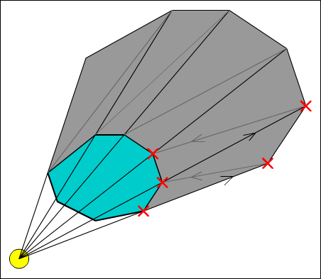
Once we have these positions, we can generate our shadow geometry. Since we are only generating hard edged shadows at the moment, we will be ignoring the physical size of our light source. Image 3 shows a how the shadow geometry is built.


Attached Image: 03HullGeneration.gif
Image 3: Hard-edged shadow generation


As shown in the image, the shadow geometry is a single triangle strip projected outwards from the back facing edges of the shadow caster. We start at the first boundary point (marked with a red cross) and work our way anti-clockwise. The second point is found by finding the vector from the light to the point, and using this to project the point away from the light. A projection scale amount is used to ensure that the edges of the shadow geometry are always off screen. For now we can simply set this to a sufficiently large number, but later it will be advantageous to calculate this every frame depending on how far zoomed in or out the camera is.

We render the shadow geometry with depth testing enabled to properly layer the shadow between various other objects in the world, but with colour writing disabled, only the alpha in the framebuffer is changed. You may remember that the final geometry pass is modulated (multiplied) by the existing alpha values, which means we need to set the shadow to have an alpha value of zero. Because the framebuffer will clamp the values to between one and zero, overlapping shadows will not make an affected area too dark but instead merge correctly.


Attached Image: 04HardShadows.gif
Image 4: Hard-edged shadows


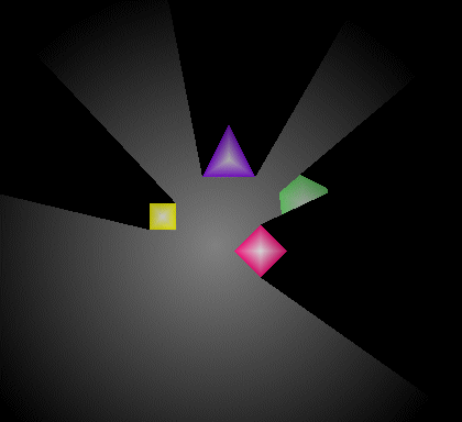
Notice in image 4 how the shadow from the diamond correctly obscures the rightmost object, and that their shadows are correctly merged where they overlap.

Soft-Edged Shadow Casting


Now we can properly construct hard edged shadows it is time to extend this to cover soft shadows – note that we cannot simply add faded edges to the existing shadow geometry, since this would result in inaccurate penumbra and umbra regions. First we start by defining a physical radius for the light source to generate the correct penumbra regions, then we need to create the penumbra geometry and modify the creation of the umbra region that we used for the hard edged shadows.

Shadow Fins


Each penumbra region will be created by one or more shadow fins via that ConvexHull and ShadowFin classes.

ShadowFin: An object to encompass all or part of a penumbra region.

Contains:
  • Root position. This is the position from which the fin protrudes from.
  • Penumbra vector. This is a vector from the root position which lies on the outer edge of the fin (the highest light intensity).
  • Umbra vector. This vector from the root position lies on the inner edge of the fin (lowest light intensity).
  • Penumbra and umbra intensities. These are the light intensities of their relative edges for the fin. If the fin makes up an entire penumbra region these are one and zero respectively.
We start at the first boundary point, and create a ShadowFin from this point. The root position becomes the boundary point, and the penumbra and umbra intensities are initially one and zero. The difficult part of the fin – the penumbra and umbra vectors – is done by the getUmbraVector and getPenumbraVector methods within our Light object.


Attached Image: 05FinGeneration.gif
Image 5: Shadow fin generation


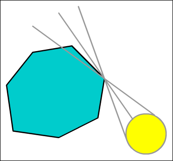
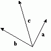
If we look at the vector that lies along the outer penumbra edge we can imagine it as the vector from the light though the boundary point (C, the centre vector) displaced by the light radius. So we must find this displacement.

First we note that the displacement is as right angles to the centre vector. So we take C and find this perpendicular vector in the same way we did to find the normals for the hull edges. Now although looking at the diagram we know which way we want this to point, when we're dealing with boundary points and light positions at all sorts of funny angles to each other we may end up with it pointing in the opposite direction to that which we expect. To solve this we find the vector from the centre of the hull to the boundary point (between the two Xs in the image), and take the dot product of this and the perpendicular vector. If this is less than zero, our vector is pointing in the wrong direction and we invert it.

Armed with this new vector we normalise it and the centre vector, then add them together and we've found our crucial outer penumbra vector. Finding the inner vector requires we repeat the process but this time we invert the logic for the dot product test to displace the centre vector in the opposite direction. We now have a fully calculated shadow fin to send to our renderer!

Non-Linear Shading


Although we have all the numbers we need to render our shadow fin, we'll soon hit a major snag – we can't use regular old vertex colours this time to write to the alpha buffer. We need the inner edge of the penumbra to be zero intensity (zero alpha) and our outer edge to be fully bright (alpha of one). While you can probably visualise that easily, getting our graphics card to actually render a triangle with the colours like this just isn't possible. Try it yourself if you're not sure, you'll soon see how it's the root point that causes the problems – it lies on both edges, so needs to be 'both' zero and one at the same time.

The solution to this (and indeed most cases when you need non linear shading) is to abandon vertex colours for the fins and instead use a texture to hold the information. Below is a copy of the texture I used.


Attached Image: 06PenumbraTexture.png
Image 6 : Penumbra texture


You can clearly see how the shadow fin will be rooted at the bottom left, and the two edges running vertical and diagonally to the top edge. Since we don't want texels from the right edge bleeding into the left we set the texture wrapping mode to clamp to the edge values (using glTexParameteri and GL_CLAMP_TO_EDGE). The bottom right half of the texture is unused, although if you really wanted to you could pack something else in here just as long as you're careful not to bleed over the edge.

So we load this texture and bind it for use before drawing our shadow fins, and set the vertex colour to white to leave the texture unchanged by it. Other than that rendering the fins is no different from the shadow hull. The only other thing we need to watch out for is how far back we project our points by the umbra/penumbra vectors, as the limited resolution of our penumbra texture will show if these are moved too far away. Ideally they will be projected to just off screen.

Modifying the umbra generation


Now we've got the fins drawn, we can fill in the umbra between them. This is done in almost exactly the same way as with hard shadows, except we must use the fins inner edges to start and finish from instead of directly projecting away from the centre of the light source. As we move across the back of the shadow caster, we perform a weighted average between these two edge vectors to properly fill in the umbra region. When done correctly we see no gaps between the fins and the umbra geometry, giving us one consistent, accurate shadow cast into the alpha buffer.

Making it robust


Self-Intersection


Now we have this far implemented, the shadows will be looking quite nice – when static – however problems will become apparent when moving the light sources around. The most glaring is that of self-intersection.


Attached Image: 07SelfIntersection.gif
Image 7: Self intersection of shadow fin


If the light source is too large in relation to the object, or too near, the inner penumbra edge will intersect the hull. First we need to detect this case. We find the vector from the boundary point to the next edge point in the shadow (moving anti clockwise here since we're on the shadow start boundary point). Then we compare the angle between the outer penumbra edge and our newly found hull edge, and the angle between the outer and inner penumbra edges. If the angle to the boundary edge is smaller, then we've got an intersection case we need to fix.

First we snap the current fin to the boundary edge, and calculate the new intensity for the inner edge via the ratio of the angles. Then we create a new shadow fin at the next point on the hull. This has an outer edge set to the same vector and intensity as the existing fins inner edge, while the new fins inner edge is calculated as before. By gluing these two fins together we create a single smooth shadow edge. Technically we should repeat the self-intersection test and keep adding more fins as needed, however I've not found that this is needed in practice.

Eliminating 'Popping'


You will also notice one other problem with this as it stands, the shadow fins will 'pop' along the edges of the hull as a light rotates. This is because we're still using an infinitely small point light to find the boundary points. To solve this we should take the physical radius into account when finding them. A robust way of doing this is to shift the light source position towards the hull by the radius distance before we find our boundary points. With these two fixes in place the fins will be visually stable as either the light or the hull moves (or both!).

Depth Offset


Depending on the style of game and the view used (such as a side scrolling platformer as opposed to a top down shooter) the way light and shadow interacts with the various level objects will be different. What seems sensible for one may appear wrong in another. Most obviously is with objects casting shadows onto objects at the same depth.


Attached Image: 08ShadowOffset.gif
Image 8: The effect of shadow offset


The image above shows the same scene with different shadow offsets. Imagine that the scene is a top down viewpoint – the light grey areas are impassable walls surrounding the floor showing a T junction (imagine hard!). Now the image on the right seems slightly out of place – the shadows are being projected on top of the walls, yet these are much higher than the light source – realistically they shouldn't be lit at all but solid black walls aren't very visually appealing. The second shows the shadows being offset and only obscuring the floor and any objects on it.

Now if you were to imagine the same scene as a 2D platformer, you might prefer the left image. Here it seems to make more sense that the objects should shadow those on the same level. This decision is usually very dependent on the geometry and art direction of the level itself, so no hard and fast rules seem to apply. The best option seems to be to experiment and see which looks best.

Adding control over this is a small modification. At the moment the scene on the left is the common case, and by generating shadow volumes that are a close fit to the edge of the shadow caster we've already done all the hard work, all we need to do is store a shadow depth offset in our ConvexHull and apply it to the depth of the shadow geometry. The existing depth testing will reject fragments drawn behind other objects and leave them at the original intensity.

Emmissive / Self Illumination pass


This is a simple addition that can produce some neat effects – and can be seen as a generalisation of the wireframe 'full-bright' pass. After the lights have been drawn, we clear the alpha buffer again as before, but instead of writing light intensities into it we render our scene geometry with their associated emissive surface. This is an alpha texture used to control light intensities as before, and can be used for glowing objects, such as a computer display or a piece of hardware with a bank of LEDs - everything that has its own light source but is too small to require an individual light of its own. Because these are so small, we skip the shadow generation and can do them all in one go. Then we modulate the scene geometry by this alpha intensity as before. Unusual effects are possible with this, such as particles which light up their immediate surroundings, or the bright local illumination provided by a neon sign (with one or two associated lights to provide the lighting at medium and long range).

Scissor Testing


We are extending the shadow geometry until it's off the edge of the screen, but often the area a light affects is much smaller than this. The scissor test (glScissor in OpenGL) allows us to restrict rendering to a rectangle within our window and avoid drawing pixels that have no effect. We just have to project the light's bounds to screen space and set the scissor area before drawing the shadow geometry. This can increase the framerate considerably.

Conclusion


After a lot of work, much maths and a few sneaky tricks and we've finally got a shadow system that's both physically accurate and robust. The hardware requirements are modest indeed – a framebuffer with an alpha component is about all that's required, we don't even need to stray into extensions to get the correct effect. There is a whole heap of possible optimisations and areas for improvement, notably caching the calculated shadow geometry when neither the light nor the caster has changed, and including some sort of spatial tree so that only the shadow casters that are actually needed are used for each light.

Notes on GameDev: Dane Olds

$
0
0
Originally published on NotesonGameDev.net
September 24, 2008


Ready for a Retro-Future with customizable characters and a wide range of new creative "homemade weapons" to blast away your nuclear waste enemies? The time is almost here! But until then, there's a range of concept art and sneak peek screenshots. In this interview we feature character artist Dane Olds, who is responsible for weapons as a character artist for Bethesda's much anticipated Fallout 3.

Fallout 3 has some very interesting customizable features that I'm sure gamers are very eager to jump into and a lot of it has to do with character art, which you're partly responsible for. Can you start off telling us a bit about how you became a character artist?

From the time I was a kid I knew I wanted to work on games. I spent a lot of time drawing my own game characters and levels. Videogames were always a source of artistic inspiration for me as a child. In high school, I started to gear myself toward getting a job in the industry. I read a lot of gaming magazines and learned as much as I could about the different jobs in the Industry. I took all the art classes I could and played a lot of games.

My first year of college was at Ivy Tech. It was a community college that had a small graphics program. There I familiarized myself with 3d Studio Max and Photoshop and started to get a real feel for computer art.

I transferred to the Savannah College of Art and design my second year of College. I enrolled in their Game Development and Interactivity program. I learned a lot about creating art specifically for games and met a lot of awesome like-minded students. My senior year a group of my friends at school set out to make a mod project for Half-Life 2 called Forever Bound. It had a Horror-Western theme and it was outside the artistic realm of what we were usually doing. We had a blast working on it even though it was an extremely short ten weeks of development time. That experience was instrumental to our transformation from students to developers.

When I graduated from SCAD I applied at as many game companies as I could and landed an internship here with Bethesda. I’ve now been with the company for over two years.

Forever Bound sounds like a game I'd want to play! Moving from your student experience to industry, where do you fit in the pipeline process at Bethesda?

I’m a character artist here at Bethesda and work primarily on weapons for Fallout 3. This often means different things. Sometimes my job is to take a piece of concept art and turn that into a game asset from scratch. Other times it involves taking a piece of outsourced art and making sure that it meets the same visual standard as the other weapons in the game. This often involves remodeling areas of a weapon, correcting for perspective, retexturing, even adding new geometry and normal maps. Each weapon presents a unique set of challenges and maintaining a visual consistency throughout all of Fallout 3’s widely varied arsenal has been an awesomely rewarding artistic challenge.

I treat each weapon just like it is an individual character in the game world. An interesting weapon has to have its own personality. At a glance the weapon should say something about its function and its role in the world. A weapon’s proportion, weight, and wear all have to be carefully considered. The worn down Hunting Rifle you find at the beginning of the game looks wildly different than a Laser Rifle you find later in the game. The Hunting Rifle is weathered and worn from its years of use in the wasteland. One look at its duct-taped Stock and rusty barrel and you know that it has seen a lot of hard use in the harshest of environments. Conversely, the sleek lines and shiny exterior of the Laser Rifle show its development in a laboratory somewhere. These two weapons share a common thread though, in their age and weathering. You can tell that they’ve both seen better days but the wear is appropriate to the individual.

The fact that our game is played from a first-person perspective as well as a third person perspective also provide a unique set of challenges from the design, right down to the creation and implementation. Every weapon has to look good when you’re running around the wasteland, staring down the barrel at a raider, or blowing enemies to bits in VATS.

That sounds like a lot to look forward to though. What was the inspiration for character art in Fallout 3?

A lot of the inspiration for the character art in Fallout 3 came from the original games. We drew heavily from those Retro-Future roots and you’ll see that throughout the character art in the game. With the weapons we always referenced the old art from Fallout. Sometimes the weapons are very close to the originals, other times they’ve been overhauled to fit specifically to the game we’ve created. A good example of this would be the Flamer. It’s functional, and is inspired by the real flame throwers used in World-War II. We take the real military designs, and then see where we can make them more interesting, what we can embellish on, and what we might need to remove. When the modeling and texturing is done we have to have something that is visually interesting and functional. Another great example is the ever-popular Power Fist. The original Power Fist was kind of an electric gauntlet. The new one has a pneumatic piston mounted on a thick steel framework that looks like an engine block. This weapon visually feels like it packs a punch, and it certainly does in the game.

Retro-Future is such a rarely used genre compared to the range of fantasy and space science fiction out there in games. With this uniqueness in mind, can you explain for us an even more unique feature of Fallout 3--the way customizing your character works?

Customizing your character in Fallout 3 works similarly to the way it did in Oblivion. When you are born in the game a “gene-projector” is used to see how you are going to look when you are an adult. This is where you tweak the myriad of choices about how you are going to look. Your complexion right down to your hairstyle is all determined here. An approximation of that data is then used to generate the way you look as a child as well as the look of your father.

Cool! What's it like creating a range of customizable character content?

Creating the range of customizable character content in the game has been uniquely challenging but very rewarding. A lot of the weapons I made for the game are ones that you create yourself in the game. The art assets themselves had to consist of items that you’d find in the game world and then assemble to form a weapon. Our concept artist did a great job figuring out the look of these cobbled together weapons which made my life a lot easier when it came time to create them for the game.

What has been the biggest challenge on Fallout 3 so far?

For me the biggest challenge while working on fallout has been the sheer volume of assets that needed to be created. Every mine, grenade, gun, and melee weapon needed its own art and the attention to detail and care given to the object had to be consistent throughout. Working through this challenge has been a great experience for me in refining my workflow. Not to mention it’s super rewarding to see all the things I’ve worked on in the game.

Aww yeah I bet. Speaking of which, what are you most proud of on Fallout 3 so far?

I’m really proud of the game as a whole. I’ve put countless hours into it already and there’s always something fun to do and a new place to explore. It’s the combined effort of the whole team that has gelled to form a game that is a blast to experience.

Personally I have a couple of favorite individual weapons I created which I probably like the most. The Power Fist really was a challenge to create. It had to act like a piece of armor that could be worn like a glove. The fingers had to articulate and the pneumatic piston had to function the way the player would expect. Creating a model that could actually animate believably and would still look cool was a pretty daunting task. I think the results speak for themselves though, a lot of people think it looks really cool and in game it really is a blast to use.

The other weapon I really like is the Flamer. I’m just happy with the way it turned out in the game. It looks great, fits right in the world and is a lot of fun to take to the battle field.

And for all those readers out there checking this out and daydreaming about your job... Any advice for artists who want to make a career out of character art in games?

Any aspiring game artist really needs to concentrate on their foundations first and foremost. If you don’t understand the fundamentals of drawing and sculpture you aren’t going to be a successful 3d modeler. Observation is key and being able to recreate what you observe in 2d is just as fundamental as being able to do the same thing in 3d.

Become extremely familiar with what it is you want to do. If you want to model pick up a 3d package and spend time in it every day. Join a forum and communicate with other 3d artist. Learn as much as you can and practice as often as you can. Be passionate about what you do and your work will speak for its self.

Play a lot of games! A good director watches a lot of movies and a good writer reads a lot of books. The same is true for game developers. The tricks and techniques you can glean from other game artist just by experiencing their work in my opinion are extremely valuable. When you play the game you are experiencing the intent of their art and the context for which it was created. This speaks volumes that a simple analysis of a model or texture cannot.

Practical Cross Platform SIMD Math

$
0
0
Math and math types are the glue which holds a game together: collision, physics, movement and a multitude of other game elements are basically just large math problems to be solved.  A well created math library is something you begin using and tend to forget about as you go, a poor library is something you continually stumble over.  There are many tutorials on basic math, library setup and architecture, there are also many tutorials about SIMD support in general.  What is rarely covered is creating a library in such a manner as to allow a scalable and multi-targeted SIMD backend with no major changes for the user.  In this article we will cover the multiple levels of Intel SSE and, as an option for Xcode, additionally target ARM Neon for iDevices.

This article is built using the environment from prior articles and as such you may want to read those.  It is not required reading as the work done here is focused on the Intel SSE instruction sets and some minor examples of ARM Neon for comparisons.  Only minor details of the build environment will need to be understood to take advantage of the presented material.  If you are interested; the prior article series can be found here: Article

Unlike prior articles, this will simply present the reader with the final library which is hosted as a live project on Google Code.  ARM Neon is discussed as a possible target but at this time the library is incomplete in that area, it will get progressively better in the future so check for updates.  The code is hosted at: code.  The directory “MathLibrary” corresponds to this article.

Terminology


For the rest of the article there is a bit of vocabulary in use which needs to be understood or things can become confusing.  First off, what is SIMD?  The terse definition is “Single Instruction Multiple Data”.  Used as such, it is referring to a subclass of instructions which the target CPU supplies.  This does not mean it is specifically Intel SSE, Power PC Altivec (VMX) or ARM Neon instructions, it is a general term to refer to the class of instructions on a given target CPU.  This article will be focused on the Intel SSE instruction set as it provides the most complicated variation, though when referring to other instruction sets, the specific name of the target will be given as: Neon, or VMX as examples.  Additionally, as SIMD refers to a set of instructions, the term will not be used when describing the process of converting normal math code to use the instructions.  Instead the generic term for applying SIMD instructions is ‘vectorization’ which is appropriate as SIMD instructions are also often referred to as vector processing.  Understanding the differences in terminology will be crucial to the remaining article.

Goals


The goal of the presented math library is to show multiple targets of SIMD instructions both based on specific CPU targets and levels of support given a target CPU.  For instance, there are at least eight different variations of SSE on Intel CPUs at this time.  Each level of SSE becomes significantly more powerful and corrects for missing items from prior versions.  For instance, SSE 1 only supports vertical concepts of manipulation.  In other words an SSE 1 based library loses considerable performance during the vectorization process due to an inability to occasionally work horizontally.  SSE 3 added horizontal manipulations, specifically add and subtract, because of how useful they are in certain contexts such as performing dot products.  Solving how to write a library which can support SSE 1 and SSE 3 (and higher) variations in a maintainable manner is one of the goals.

A secondary goal is to perform the systematic vectorization on various types yet still allow best fit selection of the underlying implementation.  Using the Steam Hardware Survey, it is possible to conclude that targeting SSE 3 is quite viable given that 99.5% of all surveyed hardware in use supports that level of SSE.  This is a simple solution and very reasonable, but what happens if you target your personal machine, enable SSE 4.2 and find that it is a very large performance gain for you?  You might go look at the survey again but this time you find support is around 50% and would make the game less broadly acceptable.  There are several solutions to this which we wish to support.  You can compile your game twice, one for SSE 3 and the other for SSE 4.2, create a little launcher app which chooses which version to load.  Another variation is to compile the game itself for SSE 3 and then move all the really heavy math portions into a shared library which can be recompiled for variations of the instruction sets which you load at runtime based on the availability of instructions.  While the details of each method are beyond the scope here, supporting them is intended to be covered.

The final goal is to expose the SIMD instruction sets in a manner where systematic optimization using vectorization is possible.  Simply vectorizing a 3D vector or a matrix is going to give notable gains, but applying vectorization to entire algorithms can make that seem trivial in comparison.  Exposing the actual SIMD instructions in a manner which allows their use without using specific knowledge of the target is going to be possible.  Of course this is quite a large topic and only the generic idea of how to approach it is covered, but the work is ready for expansion and usage in such a case.

SIMD Instruction Sets


SIMD instructions come in many forms.  If you have been using Intel CPUs for a while, you have probably watched the evolution from MMX to today's latest and greatest AVX instruction sets.  Today, if you target hand held devices (iDevices specifically in this article), the ARM Neon instruction set is a relatively recent addition to the family of SIMD instruction sets.  SIMD instruction sets are not new concepts, other processors have implemented such things for a while, the instructions are simply somewhat new to mainstream CPUs.  In this article, we will focus on the subset of instructions intended to manipulate 4 floats at a time which is fairly common to most SIMD instruction sets.

One of the difficulties with SIMD instructions is specifically caused by Intel and the way they implemented the original SSE instructions.  The intention was not to support horizontal math and they instead tried to push reorganizing data in programs to match the new instruction data layout expectations.  Sometimes this was possible to do, but often it is really not a viable approach.  As such, on the Intel CPUs, you often waste much of the performance gain with swizzling instructions.  This changed as of SSE 3 with the addition of horizontal adds and related instructions which greatly speed the handling of functionality such as dot product and magnitude calculations.  Even better, as of SSE 4.1 a single instruction dot product is available which speeds things even more in some cases.

Dealing with the multiple levels of SSE on Intel platforms is rather complicated and can lead to difficult-to-maintain code if done poorly.  Targeting a completely different set of instructions for ARM Neon is even more difficult when maintaining a uniform interface.  The similarities of the instruction sets help ease this difficulty but do not completely remove the problems.

Vectorization


Starting the process of vectorization, we need to limit our scope to something fairly simple to begin with.  At this point we are going to implement only a 3D vector class.  There will be two implementations, not counting SIMD instruction set variations.  One version is a normal C++ implementation which does not impose alignment requirements nor does it have a hidden 4th component.  The other version is the vectorized variation with all the additional impositions added.  Why two classes?  Serialization is an area where vectorized types can get in the way.  Unless you are writing a high performance binary serializer, it just doesn’t make sense to deal with the imposition of alignment and the hidden component in such a system.  Awareness of the types is of course important but different systems have different needs and forcing vectorization where it does not belong is not good practice.

The names of the classes will follow a modified version of the Open GL conventions.  The modification is simply a case of dropping the ‘gl’ prefix, since we use namespaces and modifying the postfix notations a little bit.  So, the names will be Vector3f for a 3 component floating point standard C++ vector and Vector3fv for the vectorized version.  The modified postfix naming just changes the meaning of ‘v’ from meaning a pointer to array of elements to mean vectorized.  The concepts are similar and as a pointer type doesn’t make sense in the case of a primitive, the naming change does not cause conflict.  This is not a particularly original naming convention but it works for the purposes of this article.

Initial Work Environment


In prior articles I mentioned that I had a reason for duplicating the name of a library under the ‘Include’ directory but never got into the details.  At this point we are about to use one of the reasons for the additional directory name.  Instead of coding the Vector3f and Vector3fv classes side by side, we are going to split into two separate libraries for the time being: “Math” and “Math-SIMD”.  While this is not required in general, the idea is to leverage the layout such that in a team where the primary math library could already be in use, you don’t want to introduce the vectorized types into the code base until they are ready.  Of course you also want to be continually committing your work while you go, so moving the code to the separate library keeps it out of the way for others.  But, you also don’t want to have different include paths which would have to be fixed up later when you merge the libraries.  As such, both libraries can reference “Math” files via: “#include “Math/xxx.hpp” style inclusion but obviously only when you explicitly include the ‘Math-SIMD’ library can you access the new functionality.

While this is not required, it is a handy way to work in isolation for a while.  Splitting libraries is a key feature of the build environment when discussing refactoring.  When applied to large systems, you can move sections into temporary work locations, point to the original library and the new sub-library so nothing seems as if it changed.  But, you can then make another library and rewrite a completely new version switching between implementations as needed.  This variation of the usage is not covered here but it is a large benefit to the setup.

Alignment Issues


One item to cover briefly is making sure any class which uses a vectorized math primitive can align itself in memory.  Unfortunately the state of C++11 support is still in its infancy so it is required in this case to fall back on per-compiler style alignment specifications.  Also, since this is a generic item needed through out the codebase, we will be placing it in the ‘Core’ library to be shared.  If you look in ‘Libraries/Core/Include/Core/Core.hpp’ you will see the following subsection:

//////////////////////////////////////////////////////////////////////////
// Per compiler macro's.
#if defined( COMPILER_MSVC ) || defined( COMPILER_INTEL )

#       define BEGIN_ALIGNED( n, a )                            __declspec( align( a ) ) n
#       define END_ALIGNED( n, a )

#elif defined( COMPILER_GNU ) || defined( COMPILER_CLANG )

#       define BEGIN_ALIGNED( n, a )                            n
#       define END_ALIGNED( n, a )                              __attribute__( (aligned( a ) ) )

#endif

The macro has to be split into two pieces since MSVC-style compilers and GNU-style compilers use different methods of specifying alignment.  MSVC compilers use a pre-class name ‘__declspec’ directive while GNU compilers use a postfix ‘attribute’ directive.  When C++11 is better implemented, it will be possible to remove this bit of macro trash, but until then, this is the practical solution.

There are several downsides to this solution.  It does not cover new/delete and as such if you new up a vector it will not be guaranteed to fit the alignment requirements of the underlying vectorized type.  Another problem case is putting vectors into a std::vector or other container, there is no guarantee the memory will be aligned correctly until full support of ‘alignof’ is pushed out to the compilers.  Finally, and most annoying, because we are wrapping a fundamental intrinsic type, passing an item to functions by value is not supported and may also break alignment rules.  We will be working around these problems in general but they are important to keep in mind.

SIMD Intrinsic Includes


With the ARM Neon instruction set, life is fairly simple.  There is only one include file required and no varying levels of support to be dealt with.  But this does not mean everything is simple due to the development environment for iDevices.  When targeting a real device the ARM Neon instruction set is of course supported, but when targeting the simulators they are not.  Xcode supports switching targets from the device to the simulator in the IDE, as such we need to differentiate between the targets at compile time.  This is fairly easy but does mean, on the simulator, we have to disable the Neon instruction set and fall back to non-SIMD code.  (NOTE: You could switch to Intel SSE due to this being a simulator and not an emulator, but we’ll just turn it off for now.)

Intel SSE is a bit of a can of worms as it is broken into various levels.  For ease, we don’t follow the actual levels of SSE as they progressed but instead the header file levels which Intel supplies to compilers.  The levels are thus broken down into MMX, 1, 2, 3, 3.1, 4.1, 4.2 and AVX.  While the library will not actually supply unique code for all of these levels, there will be a structure in place to allow future specialization.  Also, we list out MMX as a possible target, though it will not be used initially.  The includes in highest to lowest order, with some notes:

immintrin.h - AVX 256 bit SIMD instruction set.  (Defines __m256.)
wmmintrin.h - AVX AES instructions.
nmmintrin.h - The Core 2 Duo 4.2 SIMD instruction set.
smmintrin.h - The Core 2 Duo 4.1 SIMD instruction set.
tmmintrin.h - SSSE 3 aka SSE 3.1 SIMD instruction set.
pmmintrin.h - SSE 3 SIMD instruction set.
emmintrin.h - SSE 2 SIMD instruction set.
xmmintrin.h - SSE(1) SIMD instruction set. (Defines __m128.)
mmintrin.h - MMX instruction set.  (Defines __m64.)

The modifications to compiler options, the specifically exposed CMake options and detection of the various levels to select appropriate includes can be found in the math library environment.  Specifically dealing with the different includes and the Xcode oddities is handled in the file “Math-SIMD/Include/Math/Simd/Simd.hpp”.  It is a fairly ugly little header due to all the SSE options and the simulator difference, but it gets the job done properly.

The Intrinsic SIMD Data Type


In order to support the different target processors we need to begin abstraction of the data types.  At the same time, we are going to be implementing a fallback case for CPUs without SIMD.  In fact, implementation of the reference support is a key feature of the library.  What we are going to be writing is something similar to the SSEPlus library abstraction of the Intel intrinsics.  (See: http://sseplus.sourceforge.net)  We will only be dealing with the 4 element floating point types, so we don’t really have that many intrinsics to abstract; basic math, load/store and some manipulation abilities are all we really need.  There are exceptions we will be dealing with, but for now this is a good enough starting point.

Doing The Real Work


For the time being, we start the Vector3fv class as an empty class.  We will be refactoring this to be the vectorized version once we get some preparations out of the way.  The first step is defining how we will be working, as implied previously we are using the intrinsics and not going directly to assembly language.  Beyond just being easier, using the intrinsics provides nearly as much performance gain as hand coding assembly in this case.  In fact, with the compilers involved, quite often using the intrinsics produces faster code since register allocations are chosen to fit into surrounding code better.  Having said that, the math primitives will not be the most cutting edge and blazing fast items in the world, just a good starting point for further optimization.

Our next step is setting up the SIMD instruction set such that it is usable by the Vector3fv class (and other systems as desired) in a manner where it is an abstraction on top of the specific SIMD instructions.  There are a number of items which can be used which, beyond naming, behave pretty much identically on all the different SIMD instruction sets.  For instance, the ability to add, subtract, multiply and divide are pretty much common on each CPU and as such should be as light a wrapper as possible.  We’ll be following the same basic style of abstraction as presented in the Intel SSE intrinsics themselves, just at an extra level of abstraction.  The primary header to figure out the instruction set selection is “Include/Math/Simd/Simd.hpp”, by default it always allows use of the reference C++ implementation so even if you turn off all Simd, everything will continue to compile and function.  After inclusion, a macro is defined named: “Simd_t” which is the primary abstraction into the build selected default instruction set.  This is a macro since, as part of the goals, we want to be able to run multiple and simultaneous versions of the code based on different variations of the instruction sets, a typedef would not be able to be overridden by other code.

The first thing we need in order to use the SIMD instruction sets is a type.  The primary 4 element floating point type is defined as “Simd_t::Vec4f_t”.  The reference implementation defines this as simply a structure wrapped around a 4 element array of floats, the Intel SSE implementation defines the type as ‘__m128’ and ARM Neon defines the type as ‘float32x4_t’.  The first rule is to treat these types as completely opaque black boxes, even if you know it is an ‘__m128’, don’t go using the structure underlying the type directly, always use the “Simd_t” exposed functions.  Of course, a nice benefit to maintaining the reference library is that if you break the rules, either the reference version or whatever the active Simd instruction set implemented version will likely fail to compile.

In order to structure and maintain the multiple abstractions we add the following structure to the project:

Include/Math/Simd
Include/Math/Simd/Reference
Include/Math/Simd/Sse
Include/Math/Simd/Neon

Each new directory implements the specific instruction set and variations of each.  So, ‘Reference’ and ‘Neon’ both contain single files which expose the SIMD abstraction and ‘Sse’ contains several different files.  The content of the files end up defining structures in the namespaces as follows:

Math::Simd struct Reference;

Math::Simd struct Sse;
Math::Simd struct Sse3;
Math::Simd struct Sse4;
Math::Simd struct Avx;

Math::Simd struct Neon;

Notice that for SSE we only support 1, 3, 4 and Avx.  The reason is that, for the time being, there is no use implementing MMX, SSE2 or the inbetween versions since they add nothing significant to the math instructions.  SSE2 may be included eventually so as to support double types but this is a future extension.  Also, if you look in the supplied code, Avx derives from Sse4 which in turn derives from Sse3 etc.  We use the simple hierarchy to hide progressively lesser capable variations of the instruction set.

With all the structure out of the way, the method to use it needs to be discussed.  Our first abstraction is going to be dealing with the need to initialize SIMD types.  While all the current types we are targeting can be initialized with aggregate construction such as the following:

Simd_t::Vec4f_t  mine = {1.0f, 2.0f, 3.0f};

This leaves a bit to be desired and may also not work on future instruction sets if specialized types are introduced.  The undesirable feature of this is that the fourth component is left uninitialized and for purposes of the abstraction, we want the hidden component always to be 0.0f.  In fact, when we add debugging, asserting that the hidden component is 0.0f will be part of the checks.  So, we introduce our first abstraction function, which just happens to be the standard form for all future abstraction functions:

namespace Math
{
  namespace Simd
  {
    struct Reference
    {
      static Vec4f_t      Create( float x, float y, float z )
      {
        Vec4f_t  result  = {x, y, z, 0.0f};
        return result;
      }
    }
  }
}

The function simply creates a temporary, initializes it and returns it.  Because this is such a standard form, most compilers will completely optimize the function out of release code and the cost of the abstraction remains zero.  Visual Studio, Clang and GCC all deal with this form of optimization (often referred to as the Return Value Optimization) fairly well and only a few slower code generation mistakes result from this.  With this function in hand, it is possible to initialize our Vector3fv.

First, there is some preparation to perform.  We need to modify the Vector3fv to be an aligned class or the optimized SIMD instructions will fail:

class BEGIN_ALIGNED( Vector3fv, 16 )
{

private:
  Simd_t::Vec4f_t    mData;
} END_ALIGNED( Vector3fv, 16 );

There is still a problem though.  We don’t actually want to tie this class to the default data type based on build settings, we need to be able to change as desired.  So, we will be renaming this class and templating it as follows with a default typedef to stand in as Vector3fv:

template< Simd = Simd_t >
class BEGIN_ALIGNED( Vector3f_Simd, 16 )
{
public:
  typedef typename Simd::Vec4f_t                  ValueType_t;

private:
  ValueType_t       mData;
} END_ALIGNED( Vector3f_Simd, 16 );

typedef Vector3f_Simd< Simd_t >  Vector3fv;

With the general changes to the class behind us, let’s use the SIMD abstraction and create the constructors:

template< Simd = Simd_t >
class BEGIN_ALIGNED( Vector3f_Simd, 16 )
{
public:
  typedef typename Simd::Vec4f_t                  ValueType_t;

  Vector3f_Simd()                                                    {}
  Vector3f_Simd( const Vector3f_Simd& rhs ) : mData( rhs.mData )     {}
  Vector3f_Simd( float x, float y, float z )
  : mData( Simd::Create( x, y, z )                                   {}

private:
  ValueType_t       mData;
} END_ALIGNED( Vector3f_Simd, 16 );

typedef Vector3f_Simd< Simd_t >  Vector3fv;

A key note here is that the default constructor does not initialize to zero.  The type is intended to be used much like a fundamental float type and with the same rules.  From a class purity point of view, yes this should default initialize to zero though.  The general reason for this decision to act like a fundamental type is that compilers are still fairly weak at removing some unneeded temporary initializations and in the case of primitive math types it gets very expensive.  The class of bugs caused by this is no different than missing float and int initializations though unfortunately the compiler will not always complain about such things.  Debugging additions will be used to catch such errors later though.

Another note is that the fundamental type exposed as Vec4f_t can be copy constructed like any fundamental type.  This is critical to leverage as the compilers are able to leave types in registers longer while in use if they recognize copying and optimize appropriately.  Gcc seems to be the weakest of the compilers in this area but still does a fair job of not flushing registers until really needed.

The First SIMD Instruction


At this point we will show the first SIMD instruction abstraction.  It will also be the last individual instruction as the basics are the same for each.  We’ll look at more complicated functionality in the next section.

We will expose an operation for “Add” in the SIMD abstraction and then implement the addition operator within the vector class.  In SSE, the _mm_add_ps intrinsic (addps in assembly) is quite simple:

__m128 _mm_add_ps( __m128 lhs, __m128 rhs );

For Neon, the intrinsic is:

float32x4_t vaddq_f32( float32x4_t lhs, float32x4_t rhs );

Basically the instructions are identical except in name and type.  This makes it quite simple to implement things for all targets.

So, let’s start by implementing the reference C++ version:

// in Math::Simd::Reference:
static Vec4f_t Add( const Vec4f_t& lhs, const Vec4f_t& rhs )
{
  Vec4f_t  result =
  {
    lhs.v[ 0 ] + rhs.v[ 0 ],
    lhs.v[ 1 ] + rhs.v[ 1 ],
    lhs.v[ 2 ] + rhs.v[ 2 ],
    lhs.v[ 3 ] + rhs.v[ 3 ]
  };
  return result;
}

It is worth noting that we are passing by reference in this function but in the other abstractions we will be passing by value.  This is a minor optimization applied to the reference implementation which may or may not be required.  But in general it has no effect on usage as C++ will figure out the proper passing style be it reference or value.  Also keep in mind that while the 3rd index is hidden, we still operate on it because that is how the SIMD instructions function and we are not targeting just Vector3 but eventually 2 and 4 dimension items also.

Now the SSE implementation:

// In Math::Simd::Sse:
static Vec4f_t Add( Vec4f_t lhs, Vec4f_t rhs )
{
  return _mm_add_ps( lhs, rhs );
}

The Neon implementation:

// In Math::Simd::Neon:
static Vec4f_t Add( Vec4f_t lhs, Vec4f_t rhs )
{
  return vaddq_f32( lhs, rhs );
}

And finally the operator:

Vector3f_Simd  operator + ( const Vector3f_Simd& rhs ) const  {return Simd::Add( mData, rhs );}

If you build and compile a test which tried to use this, you would currently get an error since you can not construct a Vector3f_Simd from the fundamental SIMD type.  We will add the constructor for this, it is both required and proper.  Of course it should be noted that any conversion operator or constructor should ‘usually’ be marked explicit (conversion operators are able to be marked as such in C++11) we want to encourage passing the fundamental type around as it will pass in a register and generally be faster than passing the wrapper class.  So, in this rare occasion I leave the constructor and operator as non-explicit.

As you can see, this pattern is very easy to implement, once the conversions are handled.  We won’t perform all the repetitions here as there is nothing notable to learn from such grunt work.  Instead we move onto the more interesting bits.

The Dot Product


The dot product of two vectors is the first composite operation to be presented.  It is also a case where the different levels of Intel SSE provide additional operations which speed the computation up significantly as higher levels of SSE are used.  In order to maintain the abstraction and provide the benefits of the higher level instructions, we treat the entire dot product as a single intrinsic instead of attempting to implement it using the currently exposed intrinsic instructions.  Without getting into the details, we’ll just present the reference version of the operation to start with:

static float Dot3( const Vec4f_t& lhs, const Vec4f_t& rhs )
{
  return ( lhs.v[ 0 ]*rhs.v[ 0 ] + lhs.v[ 1 ]*rhs.v[ 1 ] + lhs.v[ 2 ]*rhs.v[ 2 ] );
}

The operation is basically a SIMD multiplication of all elements, though ignoring the hidden in this case, and then an addition of each resulting element.  From a terminology point of view, this is generally called a vertical multiply followed by a horizontal addition.  Unfortunately, the original Intel SSE did not support the horizontal operation which causes a signficant loss of performance.  The Intel SSE version is thus considerably more complex:

static float Dot3( const Vec4f_t& lhs, const Vec4f_t& rhs )
{
  static const int swap1 = _MM_SHUFFLE( 3, 3, 3, 2 );
  static const int swap2 = _MM_SHUFFLE( 3, 3, 3, 1 );
  float sresult;

  __m128 result = _mm_mul_ps( lhs, rhs );
  __m128 part1  = _mm_shuffle_ps( result, result, swap1 );
  __m128 part2  = _mm_shuffle_ps( result, result, swap2 );

  result = _mm_add_ps( result, part1 );
  result = _mm_add_ps( result, part2 );

  _mm_store_ss( &sresult, result );
  return sresult;
}

Without getting into details, after multiplying the individual components, we have to swap things around a bit in order to add them all together and then store the result.  While generally faster than the reference version, it is not a major win due to the swizzle instructions.  Thankfully, in steps the SSE 3 version though, at nearly half the cycle count:

static float Dot3( const Vec4f_t& lhs, const Vec4f_t& rhs )
{
  float sresult;

  __m128 result = _mm_mul_ps( lhs, rhs );
  result  = _mm_hadd_ps( result, result );
  result  = _mm_hadd_ps( result, result );

  _mm_store_ss( &sresult, result );
  return sresult;
}

Finally, with SSE 4, Intel implemented the entire thing for us:

static float Dot3( const Vec4f_t& lhs, const Vec4f_t& rhs )
{
  float sresult;
  __m128 result = _mm_dp_ps( lhs, rhs, 0x77 );
  _mm_store_ss( &sresult, result );
  return sresult;
}

By inserting these functions into the library of support files and structures, we have access to a per target optimized dot product.  By expecting only that the container classes are properly aligned, the implementation of the vector type becomes identical to the non-vectorized version when finished.  The level of abstraction is a bit fine grained but we are using assembly language instructions, which are about as fine grained as possible anyway, we are actually stepping back just a bit to contain complete concepts.  Further extensions such as performing transformations on entire buffers can be done as single abstractions and optimized heavilly for each target, the speed increases compared to vectorizing just the Vector3 types is fairly impressive in comparison.


Conclusion


With the example implementation and the overview, hopefully this has given you a method of using a SIMD math library in a manner which does not intrude on everyday work.  While not a particularly long or detailed article, the overview of the design and architecture of the code should provide a simple to follow pattern which extends to nearly any specialized math processing which can be used in general purpose programming.  The example library will be fleshed out and expanded on for the next article in which it will be used further.  At that time I will also be introducing a simple testbed for the library which will become a benchmarking item for future work.

Vectors and Matrices: A Primer

$
0
0

Preface


This article is designed for those who need to brush up on your maths. Here we will discuss vectors, the operations we can perform on them, and why we find them so useful. We’ll then move onto what matrices and determinants are, and how we can use them to help us solve systems of equations. Finally, we’ll move onto using matrices to define transformations in space.

Note:  
This article was originally published to GameDev.net back in 2002. It was revised by the original author in 2008 and published in the book Beginning Game Programming: A GameDev.net Collection, which is one of 4 books collecting both popular GameDev.net articls and new original content in print format.


Vectors


Vector Basics – What is a vector?


Vectors are the backbone of games. They are the foundation of graphics, physics modelling, and a number of other things. Vectors can be of any dimension, but are most commonly seen in two, three, or four dimensions. They essentially represent a direction, and a magnitude. Thus, consider the velocity of a ball in a football game. It will have a direction (where it's travelling), and a magnitude (the speed at which it is travelling). Normal numbers (i.e. single dimensional numbers) are called scalars.

The notation for a vector is that of a bold lower-case letter, like i, or an italic letter with an underscore, like i. I'll use the former in this text. You can write vectors in a number of ways, however I'll only use two here: vector equations and column vectors.

Vectors can be written in terms of its starting and ending position, using the two end points with an arrow above them. So, if you have a vector between the two points A and B, you can write that as:

Attached Image: ccs-8549-0-74933000-1311406833_thumb.gif

A vector equation takes the form:

a = xi + yj + zk

The coefficients of the i, j, and k parts of the equation are the vectors components. These are how long each vector is in each of the 3 axis.

For example, the vector equation pointing to the point ( 3, 2, 5 ) from the origin ( 0, 0, 0 ) in 3D space would be:

a = 2i + 3j + 5k

The second way I will represent vectors is as column vectors. These are vectors written in the following form:

Attached Image: ccs-8549-0-13322100-1311406871_thumb.gif

Where x, y, and z are the components of that vector in the respective directions. These are exactly the same as the respective components of the vector equation. Thus in column vector form, the previous example could be written as:

Attached Image: ccs-8549-0-41119900-1311406881_thumb.gif

There are various advantages to both of the above forms, although column vectors will continue to be used. Various mathematic texts may use the vector equation form.

Vector Mathematics


There are many ways in which you can operate on vectors, including scalar multiplication, addition, scalar product, vector product and modulus.

Modulus

The modulus or magnitude of a vector is simply its length. This can easily be found using Pythagorean Theorem with the vector components. The modulus is written like so:

a = |a|

Given:

Attached Image: ccs-8549-0-13322100-1311406871_thumb.gif

Then,

Attached Image: ccs-8549-0-18438000-1311406906_thumb.gif

Where x, y and z are the components of the vector in the respective axis.

Addition

Vector addition is rather simple. You just add the individual components together. For instance, given:

Attached Image: ccs-8549-0-52337300-1311406947_thumb.gif
        
The addition of these vectors would be:

Attached Image: ccs-8549-0-28558500-1311406958_thumb.gif

This can be represented very easily in a diagram, for example:
  
Attached Image: ccs-8549-0-12549800-1311406970_thumb.gif Attached Image: ccs-8549-0-52518500-1311406982_thumb.gif
Attached Image: ccs-8549-0-25839100-1311406994_thumb.gif

This works in the same way as moving the second vector so that its beginning is at the first vector's end, and taking the vector from the beginning of the first vector to the end of the second one. So, in a diagram, using the above example, this would be:

Attached Image: ccs-8549-0-06202600-1311407005_thumb.gif

This means that you can add multiple vectors together to get the resultant vector. This is used extensively in mechanics for finding resultant forces.

Subtracting

Subtracting is very similar to adding, and is also quite helpful. The individual components are simply subtracted from each other. The geometric representation however is quite different from addition. For example:

Attached Image: ccs-8549-0-83651900-1311407019_thumb.gif Attached Image: ccs-8549-0-31746600-1311407031_thumb.gif
Attached Image: ccs-8549-0-13826600-1311407045_thumb.gif

The visual representation is:

Attached Image: ccs-8549-0-75087900-1311407058_thumb.gif

Here, a and b are set to be from the same origin. The vector c is the vector from the end of the second vector to the end of the first, which in this case is from the end of b to the end of a.

It may be easier to think of this as a vector addition, where instead of having:

c = ab

We have:

c = -b + a

Which according to what was said about the addition of vectors would produce:

Attached Image: ccs-8549-0-75087900-1311407058_thumb.gif

You can see that putting a on the end of –b has the same result.

Scalar Multiplication

This is another simple operation; all you need to do is multiply each component by that scalar. For example, let us suggest that you have a vector a and a scalar k. To perform a scalar multiplication you would multiply each component of the vector by that scalar, thus:

Attached Image: ccs-8549-0-13322100-1311406871_thumb.gif

Attached Image: ccs-8549-0-84633600-1311407105_thumb.gif

This has the effect of lengthening or shortening the vector by the amount k. For instance, take k = 2; this would make the vector a twice as long. Multiplying by a negative scalar reverses the direction of the vector.

The Scalar Product (Dot Product)

The scalar product, also known as the dot product, is very useful in 3D graphics applications. The scalar product is written:

Attached Image: dot.png

This is read “a dot b”.

The definition of the scalar product is:

Attached Image: scalar.png

Θ is the angle between the two vectors a and b. This produces a scalar result, hence the name scalar product. This operation has the result of giving the length of the projection of a on b. For example:

Attached Image: BegGameProg_VectorsAndMatricesAPrimer_Dadd_5.jpg

The length of the thick gray horizontal line segment would be the dot product.

The scalar product can also be written in terms of Cartesian components as:

Attached Image: ccs-8549-0-11366200-1311407231_thumb.gif Attached Image: ccs-8549-0-25055400-1311407243_thumb.gif
Attached Image: ccs-8549-0-12617400-1311407255_thumb.gif

We can put the two dot product equations equal to each other to yield:

Attached Image: ccs-8549-0-33111200-1311407287_thumb.gif

With this, we can find angles between vectors.

Scalar products are used extensively in the graphics pipeline to see if triangles are facing towards or away from the viewer, whether they are in the current view (known as frustum culling), and other forms of culling.

The Vector Product (Cross Product)

The vector product, also commonly known as the cross product, is one of the more complex operations performed on vectors. In simple terms, the vector product produces a vector that is perpendicular to the vectors having the operation applied. Great for finding normal vectors to surfaces!

Attached Image: BegGameProg_VectorsAndMatricesAPrimer_Dadd_6.jpg

I’m not going to get into the derivation of the vector product here, but in expanded form it is:

Attached Image: index.gif

Read “a cross b”.

Since the cross product finds the perpendicular vector, we can say that:

i x j = k

j x k = i

k x i = j

Note that the resultant vectors are perpendicular in accordance with the “right hand screw rule”. That is, if you make your thumb, index and middle fingers perpendicular, the cross product of your middle finger with your thumb will produce your index finger.

Using scalar multiplication along with the vector product we can find the "normal" vector to a plane. A plane can be defined by two vectors, a and b. The normal vector is a vector that is perpendicular to a plane and is also a unit vector. Using the formulas discussed earlier, we have:

c = a x b

Attached Image: ccs-8549-0-47469800-1311407367_thumb.gif

This first finds the vector perpendicular to the plane made by a and b then scales that vector so it has a magnitude of 1.

One important point about the vector product is that:

Attached Image: index.gif

This is a very important point. If you put the inputs the wrong way round then you will not get the correct normal.

Unit Vectors

These are vectors that have a unit length, i.e. a modulus of one. The i, j and k vectors are examples of unit vectors aligned to the respective axis. You should now be able to recognise that vector equations are quite simply just that. Adding together 3 vectors scaled by varying degrees to produce a single resultant vector.

To find the unit vector of another vector, we use the modulus operator and scalar multiplication like so:

Attached Image: UV1.png

For example:

Attached Image: UV2.png

Attached Image: UV3.png

Attached Image: UV4.png

That is the unit vector b in the direction of a.

Position Vectors

These are the only type of vectors that have a position to speak of. They take their starting point as the origin of the coordinate system in which they are defined. Thus, they can be used to represent points in that space.

The Vector Equation of a Straight Line

The vector equation of a straight line is very useful, and is given by a point on the line and a vector parallel to it:

Attached Image: index.gif

Where p0 is a point on the line, and v is the unit vector giving its direction. t is called the parameter and scales v. From this you can see that as t varies a line is formed in the direction of v.

Attached Image: BegGameProg_VectorsAndMatricesAPrimer_Dadd_7.jpg

This equation is called the parametric form of a straight line. Using this to find the vector equation of a line through two points is easy:

Attached Image: ccs-8549-0-39434100-1311407462_thumb.gif

If t is constrained to values between 0 and 1, then we have a line segment starting at the point p0 and p1.

Using the vector equation we can define planes and test for intersections. A plane can be defined as a point on the plane, and two vectors that are parallel to the plane.

Attached Image: ccs-8549-0-74851200-1311407475_thumb.gif

Where s and t are the parameters, and u and v are the vectors that are parallel to the plane. Using this, you can find the intersection of a line and a plane, as the point of intersection must line on both the plane at the line. Thus, we simply make the two equations equal to each other.

Given the line and plane:

Attached Image: vline1.png

To find the intersection we equate so that:

Attached Image: vline2.png

We then solve for w, s and t, and plug them into either the line or plane equation to find the point. When testing for a line segment w must be in the range 0 to 1.

Another representation of a plane is the normal-distance. This combines the normal of the plane, and its distance from the origin along that normal. This is especially useful for finding out what sides of a plane points are. For example, given the plane p and point a:

Attached Image: ccs-8549-0-11366200-1311407231_thumb.gif

p = n + d

Where,

Attached Image: neq.png

The point a is in front of the plane p if:

Attached Image: neq2.png

This is used extensively in various culling mechanisms.

Matrices


What is a Matrix anyway?


A matrix can be considered a 2D array of numbers, and take the form:

Attached Image: ccs-8549-0-61157600-1311407567_thumb.gif

Matrices are very powerful, and form the basis of all modern computer graphics. We define a matrix with an upper-case bold type letter, as shown above. The dimension of a matrix is its height followed by its width, so the above example has dimension 3x3. Matrices can be of any dimensions, but in terms of computer graphics, they are usually kept to 3x3 or 4x4. There are a few types of special matrices; these are the column matrix, row matrix, square matrix, identity matrix and zero matrix. A column matrix is one that has a width of 1, and a height of greater than 1. A row matrix is a matrix that has a width of greater than 1, and a height of 1. A square matrix is when the dimensions are the same. For instance, the above example is a square matrix, because the width equals the height. The identity matrix is a special type of matrix that has values in the diagonal from top left to bottom right as 1 and the rest as 0. The identity matrix is known by the letter I, where:

Attached Image: ccs-8549-0-35181600-1311407600_thumb.gif

The identity matrix can be any dimension, as long as it is also a square matrix.

The elements of a matrix are all the numbers within it. They are numbered by the row/column position such that:

Attached Image: ccs-8549-0-86930600-1311407611_thumb.gif

The zero matrix is one that has all its elements set to 0.

Vectors can also be used in column or row matrices. I will use column matrices here, as that is what I have been using in the previous section. A 3D vector a in matrix form will use a matrix A with dimension 3x1 so that:

Attached Image: ccs-8549-0-72535500-1311407625_thumb.gif

Which as you can see is the same layout as using column vectors.

Matrix Arithmetic


I’m not going to go into every possible matrix manipulation (we would be here some time), instead I’ll focus on the important ones.

Scalar / Matrix Multiplication

To perform this operation all you need to do is simply multiply each element by the scalar. Thus, given matrix A and scalar k:

Attached Image: scalarX.png

Attached Image: scalarX2.png

Matrix / Matrix Multiplication

Multiplying a matrix by another matrix is more difficult. First, we need to know if the two matrices are conformable. For a matrix to be conformable with another matrix, the number of rows in A needs to equal the number of columns in B. For instance, take matrix A as having dimension 3x3 and matrix B having dimension 3x2. These two matrices are conformable because the number of rows in A is the same as the number of columns in B. This is important as you'll see later. The product of these two matrices is another matrix with dimension 3x2.

So generally, given three matrices A, B and C, where C is the product of A and B. A and B have dimension mxn and pxq respectively. They are conformable if n=p. The matrix C has dimension mxq. It is said that the two matrices are conformable if their inner dimensions are equal (n and p here).

The multiplication is performed by multiplying each row in A by each column in B. Given:

Attached Image: ccs-8549-0-58828200-1311407689_thumb.gif Attached Image: ccs-8549-0-75807400-1311407700_thumb.gif

Attached Image: index.gif

So, with that in mind let us try an example!
      
Attached Image: ccs-8549-0-79987200-1311407726_thumb.gif  Attached Image: ccs-8549-0-00678700-1311407738_thumb.gif

Attached Image: index.gif

It’s as simple as that! Some things to note:

Attached Image: ccs-8549-0-29109000-1311407760_thumb.gif

A matrix multiplied by the identity matrix is the same, so:

AI = IA = A

The Transpose

The transpose of a matrix is it flipped along the diagonal from the top left to the bottom right and is denoted by using a superscript T, for example:

Attached Image: ccs-8549-0-93459600-1311407784_thumb.gif

Attached Image: ccs-8549-0-35495300-1311407805_thumb.gif

Determinants


Determinants are a useful tool for solving certain types of equations, and are used rather extensively.

Let’s take a 2x2 matrix A:

Attached Image: ccs-8549-0-76083400-1311407842_thumb.gif

The determinant of matrix A is written |A| and is defined to be:

Attached Image: ccs-8549-0-61430500-1311407863_thumb.gif

That is the top left to bottom right diagonal multiplied together subtracting the top right to bottom left diagonal. Things get a bit more complicated with higher dimensional determinants, let us discuss a 3x3 determinant first. Take A as:

Attached Image: ccs-8549-0-93920700-1311407878_thumb.gif

Step 1: move to the first value in the top row, a11. Take out the row and column that intersects with that value.

Attached Image: ccs-8549-0-41315500-1311407890_thumb.gif

Step 2: multiply that determinant by a11.

Attached Image: ccs-8549-0-76373600-1311407901_thumb.gif

We repeat this along the top row, with the sign in front of the result of step 2 alternating between a “+” and a “-“. Given this, the determinant of A becomes:

Attached Image: index.gif

Now, how do we use these for equation solving? Good question.

Given a pair of simultaneous equations with two unknowns:

Attached Image: ccs-8549-0-36208700-1311407930_thumb.gif

We first push these coefficients of the variables into a determinant, producing:

Attached Image: ccs-8549-0-95740300-1311407941_thumb.gif

You can see that it is laid out in the same way. To solve the equation in terms of x, we replace the x coefficients in the determinant with the constants k1 and k2, dividing the result by the original determinant:

Attached Image: det1.png

To solve for y we replace the y coefficients with the constants instead. This algorithm is called Cramers Rule.

Let’s try an example to see this working, given the equations:

Attached Image: det2.png

We push the coefficients into a determinant and solve:

Attached Image: det3.png

To find x substitute the constants into the x coefficients, and divide by D:

Attached Image: det4.png

To find y substitute the constants into the y coefficients, and divide by D:

Attached Image: det5.png

It’s as simple as that! For good measure, let’s do an example using 3 unknowns in 3 equations:

Attached Image: det6.png

Solve for x:

Attached Image: det7.png

Solve for y:

Attached Image: det8.png

Solve for z:

Attached Image: det9.png

And there we have it, how to solve a series of simultaneous equations using determinants, something that can be very useful.

Matrix Inversion

Equations can also be solved by inverting a matrix. Using the same equations as before:

Attached Image: ccs-8549-0-56571200-1311408118_thumb.gif

We first push these into three matrices to solve:

Attached Image: ccs-8549-0-90083900-1311408131_thumb.gif
  
Let’s give these names such that:

Attached Image: ccs-8549-0-02710700-1311408147_thumb.gif

We need to solve for B (this contains the unknowns after all). Since there is no “matrix divide” operation, we need to invert A and multiply it by D such that:

Attached Image: ccs-8549-0-35483900-1311408160_thumb.gif

Now we need to know how to actually do the matrix inversion. There are many ways to do this, and the way that I’m going to use here is by no means the fastest.

To find the inverse of a matrix, we need to first find its co-factor. We use a method similar to what we used when finding the determinant. What you do is this: at every element, eliminate the row and column that intersects it, and make it equal the determinant of the remaining part of the matrix, multiplied by the following expression:

Attached Image: index.gif

Where i and j is the position in the matrix.

For example, given a 3x3 matrix A, and its co-factor C. To calculate the fist element in the cofactor matrix (c11), we first need to get rid of the row and column that intersects this so that:

Attached Image: ccs-8549-0-44070200-1311408176_thumb.gif

c11 would then take the value of the following:

Attached Image: fig.png

We would then repeat for all elements in matrix A to build up the co-factor matrix C. The inverse of matrix A can then be calculated using the following formula.

Attached Image: ccs-8549-0-23509400-1311408221_thumb.gif

The transpose of the co-factor matrix is also referred to as the adjoint.

Given the previous example and equations, let’s find the inverse matrix of A.

Firstly, the co-factor matrix C would be:

Attached Image: index.gif

Attached Image: ccs-8549-0-53635100-1311408248_thumb.gif

|A| is:

|A| = -2

Thus, the inverse of A is:

Attached Image: inverse.png

We can then solve the equations by using:

Attached Image: ccs-8549-0-36524500-1311408291_thumb.gif

Attached Image: index.gif

We can find the values of x, y and z by pulling them out of the resultant matrix, such that:

x = -62

y = 39

z = 3

Which is exactly what we got by using Cramer’s rule!

Matrices are said to be orthogonal if its transpose equals its inverse, which can be a useful property to quick inverting of matrices.

Matrix Transformations


Graphics APIs use a set of matrices to define transformations in space. A transformation is a change, be it translation, rotation, or whatever. Using position vector in a column a matrix to define a point in space, a vertex, we can define matrices that alter that point in some way.

Transformation Matrices

Most graphics APIs use three different types of primary transformations. These are translation; scaling; and rotation. We can transform a point p using a transformation matrix T to a point p' like so:

p' = Tp

We use 4 dimensional vectors from now on, of the form:

Attached Image: 4d.png

We then use 4x4 transformation matrices. The reason for the 4th component here is to help us perform translations using matrix multiplication. These are called homogeneous coordinates. I won’t go into their full derivation here, as that is quite beyond the scope of this article (their true meaning and purpose comes from points in projective space).

Translation

To translate a point onto another point, there needs to be a vector of movement, so that:

Attached Image: BegGameProg_VectorsAndMatricesAPrimer_Dadd_8.jpg

Where p’ is the translated point, p is the original point and v is the vector along which the translation has taken place.

By keeping the w component of the vector as 1, we can represent this transformation in matrix form as:

Attached Image: transform.png

Scaling

You can scale a vertex by multiplying it by a scalar value, such that:

Attached Image: index.gif

Where k is the scalar constant. You can multiply each component of p by a different constant. This will make it so you can scale each axis by a different amount.

In matrix form this becomes:

Attached Image: scaling.png

Where kx, ky, and kz are the scaling factors in the respective axis.

Rotation

Rotation is a more complex transformation, so I’ll give a more thorough derivation for this than I have the others.

Rotation in a plane (i.e. in 2D) can be described in the following diagram:

Attached Image: BegGameProg_VectorsAndMatricesAPrimer_Dadd_10.jpg

This diagram shows that we want to rotate some point p by ω degrees to point p'. From this we can deduce the following equations:

Attached Image: rotation.png

We are dealing with rotations about the origin, thus the following can be said:

|P'| = |P|

Using the trigonometric identities for the sum of angles:

Attached Image: rotation2.png

We can expand the previous equations to:

Attached Image: rotation3.png

From looking at the diagram, you can also see that:

Attached Image: rotation4.png

Substituting those into our equations, we end up with:

Attached Image: rotation5.png

Which is what we want (the second point as a function of the first point).

We can then push this into matrix form:

Attached Image: rotation6.png

Here, we have the rotation matrix for rotating a point in the x-y plane. We can expand this into 3D by having three different rotation matrices, one for rotating along the x axis, one in the y axis, and another for the z axis (this one is effectively what we have just done). The unused axis in each rotation remains unchanged. These rotation matrices become:

Attached Image: rotation7.png

Attached Image: rotation8.png

Any rotation about an axis by θ can be undone by a successive rotation by –θ, thus:

Attached Image: rotation9.png

Also, notice that the cosine terms are always on the top left to bottom right diagonal, and notice the symmetry of the sine terms along this axis. This means, we can also say:

Attached Image: rotation10.png

Rotation matrices that act upon the origin are orthogonal.

One important point to consider is the order of rotations (and transformations in general). A rotation along the x axis followed by a rotation along the y axis is not the same as if it were applied in reverse. Similarly, a translation followed by a rotation does not produce the same result as a rotation followed by a translation.

Frames

A frame can be considered a local coordinate system, or frame of reference. That is, a set of three basis vectors (unit vectors perpendicular to each other), plus a position, relative to some other frame. So, given the basis vectors and position:

Attached Image: frames.png
    
That is a, b, and c defines the basis vectors, with p being its position.

We can push this into a matrix, defining the frame, like so:

Attached Image: frames2.png

This matrix is useful, as it lets us transform points into a second frame – so long as those points exist in the same frame as the second frame. Thus, consider a point in some frame:

Attached Image: frames3.png
  
Assuming the frame we defined above is in the same frame as that point, we can transform this point to be in our frame like so:

Attached Image: frames4.png

That is:

Attached Image: frames5.png

Which if you think about it is what you would expect. If you have a point at -1 along the x axis, and you transform it into a frame that is at +1 along the x axis and orientated the same, then relative to that second frame the point appears at -2 along its x axis.

This is useful for transforming vertices between different frames, and is incredibly useful for having objects moving relative to one frame, while that frame itself is moving relative to another one. You can simply multiply a vertex first by its parent frame, then by its parents frame, and so forth to eventually get its position in world space, or the global frame.

You can also use the standard transformation matrices previously to transform frames with ease. For instance, we can transform the above frame to rotate by 90º along the y axis like so:

Attached Image: frames6.png

This is exactly what you would expect (the z axis to move to where the x axis was, and the x axis point in the opposite direction to the original z axis).

Summary


Well that’s it for this article. We’ve gone through what vectors are, the operations that we can perform on them and why we find them useful. We then moved onto matrices, how they help us solve sets of equations, including how to use determinants. We then moved on to how to use matrices to help us perform transformations in space, and how we can represent that space as a matrix.

I hope you’ve found this article useful!

References


Interactive Computer Graphics – A Top Down Approach with OpenGL – Edward Angel

Mathematics for Computer Graphics Applications – Second Edition – M.E Mortenson

Advanced National Certificate Mathematics Vol.: 2 – Pedoe

Game Development with Win32 and DirectX 11 - Part 01: The Basic Framework
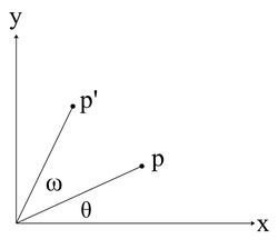
$
0
0

Introduction


Alright, now its time to get our hands dirty in some code. Before we move forward, please make sure you have read the first lesson in this series where we get all our prerequisites in order.

Let's Get Our Project Setup


So before we can actually start writing code, we'll need to get a Visual Studio project up and running. I'm expecting that by now, you already have Visual Studio open (if not please do so) and maybe you've already played around with it a bit. If you already understand how to setup a Win32 executable project in Visual Studio, please do so and then scroll down to the Project Settings sub-section.

Creating our Project


With Visual Studio open, click on File in the menubar. Then select New, Project.

Attached Image: File-New-Project.png

The New Project dialog should now open. Now this dialog can vary slightly, depending on the version of Visual Studio you are using (Express or Pro/Pre/Ult). In any case, you are going to want to find the Visual C++ tree, from the Install Templates sidebar. Under Visual C++, you are going to want to select Win32, Win32 Project. At the bottom of the dialog, select your solution name, and the directory in which you want to store it. Now, when you click Ok, the Win32 Application Wizard will appear.

In the wizard, click next to go ahead to the second page. Here is where we will decide what type of project we want to create. Since we want our game to run in a window, without the console showing up, we are going to select "Windows Application". Below that, you are going to want to select "Empty Project". Once all these settings are setup properly, you can go ahead and click Finish to generate your project.

Attached Image: Win32-Application-Wizard.PNG

Project Settings


Alright, now we have a working project. Before we go ahead and start coding, lets make some changes to the default settings for this project so that it better suits our needs.

Solution Organization

Before we get into the nitty-gritty settings, lets just make a small change to the organization of the Solution Explorer. You might notice that there are currently three file filters, Header Files, Resource Files, and Source Files (ignore External Dependencies for now). Different developers have different ways of organizing this project files. I've found that the most easy to use and organized way is to have each module of our game be located in a separate filter structure. So I took the project layout from this:

Attached Image: Solution-Explorer-Structure-Before.PNG

To:

Attached Image: Solution-Explorer-Structure-After.PNG

You can delete filters by clicking on the first one and then shift-clicking on the last one then pressing delete (a little dialog will popup, just click Ok). To add new filters, right click on the Project, select Add, then New Filter.

Attached Image: Project-Add-New-Filter.png

We really don't have to change any real settings just yet. We make some changes later on in this series though.

Time for Some Coding


Now that you have a properly setup project running, we can start coding. The way we are going to build our game is extremely simple. Now take note that this isn't your standard, single-file tutorial, we will be creating more and more files as the series progresses (that's why it's really important to use an IDE so you can keep everything organized). So with that in mind, let's begin.

Framework Design


Alright, so I lied. We aren't going to start coding just yet (but very soon). Before we get coding, I want to make sure you understand how we are going to build our game. Our game is going to consist of multiple modules:
  • Main: Not really a module, but it loads all the other modules and makes sure they are working properly.
  • Input: The input module will handle all keyboard and mouse (and eventually other devices) inputs.
  • Graphics: Probably the most interesting one for most of you, this will be a very lightweight wrapper around Direct3D 11.
  • Sound: Loads and plays sounds through XAudio2.
  • Game: The primary connection between the other modules and the Main module.
  • Scene: A simple scene-graph that is designed to be easily expandable.
Now, without further ado, let's get our hands dirty in some code!

Note:  In order to keep this article reasonably short, the complete source code will not be posted here. Rather, I will provide links to the source files which will be hosted on GitHub. Any source code written in here is to highlight a notable peice of code. Also, comments will not be placed in the embedded code snippets (GitHub contains fully-commented code).


Input


Ok, so first we'll start with the input module. For now, we aren't going to add too much meat to the modules. This is going to be one of the easiest modules to work with. Right now, we are only going to have 3 methods:

InputModule(void);

bool Initialize(void);
void Shutdown(void);

Header File Declaration
Source File Definition

Graphics


Next up is the graphics module. We are going to do the same thing as what we did with the input module.

GraphicsModule(void);

bool Initialize(void);
void Shutdown(void);

Header File Declaration
Source File Definition

Sound


Our sound module is going to follow the same pattern.

SoundModule(void);

bool Initialize(void);
void Shutdown(void);

Header File Declaration
Source File Definition

Scene


Finally, our scene-graph module will be the last to follow the same pattern.

SceneModule(void);
    
bool Initialize(void);
void Shutdown(void);

Header File Declaration
Source File Definition

Game


Alright, time for some real programming. First, let's include our different modules and the Win32 Api.

    
#define WIN32_LEAN_AND_MEAN
#include <Windows.h>

#include "InputModule.h"
#include "GraphicsModule.h"
#include "SoundModule.h"
#include "SceneModule.h"

Now let's declare and define our methods, but let's do it a little differently this time.

GameModule(InputModule input, GraphicsModule graphics, SoundModule sound);
    
void Initialize(HINSTANCE instance);
void Shutdown(void);

void Show(bool show);

int MainLoop(MSG *msg);

Header File Declaration
Source File Definition

Now, let's add a few private module pointers.

InputModule *inputPtr;
GraphicsModule *graphicsPtr;
SoundModule *soundPtr;
SceneModule *scenePtr;

HWND window;
WNDCLASSEX wndClass;

Header File Declaration

Lastly, let's make a couple global things:

static RECT windowSize = { 0, 0, 1280, 720 };

LRESULT CALLBACK WndProc(HWND wnd, UINT message, WPARAM wParam, LPARAM lParam);

Header File Declaration
Source File Definition

Main


Now comes our final piece of code, the WinMain function.

int WINAPI WinMain(HINSTANCE instance, HINSTANCE prevInstance, LPSTR cmdLine, int cmdShow) {
    MSG msg;
    
    InputModule input = InputModule();
    GraphicsModule graphics = GraphicsModule();
    SoundModule sound = SoundModule();
    SceneModule scene = SceneModule();
    
    GameModule game = GameModule(input, graphics, sound, scene);
    
    game.Initialize();
    
    game.Show(true);
    
    if (!game.MainLoop(&msg)) {
        game.Show(false);
        game.Shutdown();
        
        return static_cast<int>(msg.wParam);
    }
    
    return 0;
}

Source File Definition

Compiling


You should now be able to compile your code. And have a result that is similar to the following:

Attached Image: Results.png

Project Source Code


If you would like to take a look at the complete source code for this lesson, please visit the official source code repository for this tutorial series, hosted on GitHub. I will also upload the source code as an attachment to this article, but it will not be updated with any bug-fixes or post-publication edits.

Lesson Tasks


Please perform the following actions to prepare yourself for the next tutorial:

  1. Change the code in GameModule::Initialize() to make one of the error message boxes show up (make sure to change it back once you are done to prepare for the next lesson).

Coming Up...


In the next tutorial, we'll begin adding some meat to our currently empty framework.

Math for Game Developers: Intro to Vectors

$
0
0
Math for Game Developers is exactly what it sounds like - a weekly instructional YouTube series wherein I show you how to use math to make your games. Every Thursday we'll learn how to implement one game design, starting from the underlying mathematical concept and ending with its C++ implementation. The videos will teach you everything you need to know, all you need is a basic understanding of algebra and trigonometry. If you want to follow along with the code sections, it will help to know a bit of programming already, but it's not necessary.

Starting with the second series, "Advanced Vectors" (coming next week to GDnet but already available on YouTube), you can download the source code that I'm using from GitHub, from the description of each video. If you have questions about the topics covered or requests for future topics, I would love to hear them! Leave a comment, or ask me on my Twitter, @VinoBS

Note:  
The video below contains the playlist for all the videos in this series, which can be accessed via the playlist bar atop the timeline scrubber or the icon in the bottom-right corner of the embedded video frame. The first video in the series is loaded automatically


Intro to Vectors


Swept AABB Collision Detection and Response

$
0
0
Collision detection is an area of game development that scares most into using third party physics APIs due to its seemingly vertically-steep learning curve. Most programmers understand the axis-aligned bounding box (AABB) algorithm but have trouble transitioning to the more difficult algorithms such as SAT and GJK. Swept AABB is the middle player that will show a lot of the problems that can occur with normal AABB and help understand core concepts used in more advanced collision techniques.

Note:  This article assumes you understand the AABB algorithm. There is also a bit of vector math, but it won’t get overly complicated. Examples are done in C/C++ but can be easily converted to other languages. At the end, I have given source files for C/C++ and C#.


What is Swept?


AABB has a major fundamental problem that may not be visible at first. Take these 3 examples:


Attached Image: 01.png

Example 1: A normal AABB collision. The blue box is where the box is at the beginning of the frame. The green box is where the box is expected to be by the end of the frame. The aqua box shows where AABB will place the box after collision. The gray box is a static (unmovable) block that is tested for collision. This shows a normal collision. The box is moved to the nearest point that is not a collision. This is fine and is the expected result of AABB.


Attached Image: 02.png

Example 2 shows a similar collision where the destination is further on the opposite side. As you can see, AABB has placed the response box on the opposite side of the block. Logically, this makes no sense as it has magically passed through the object.


Attached Image: 03.png

Example 3 shows a destination that doesn’t collide with the object. AABB will assume that there was no collision and the moving box will move through it like there was no collision at all.

So when do these problems occur?

These problems usually appear when objects are moving fast and/or the program is running at a low frame rate. To avoid this, we need to somehow predict where the box travelled between each frame. This concept is called swept.

Implementing Swept AABB


In this implementation, we will assume that a box is defined by a position at the top-left corner of the box and a width and height. Now that we are taking swept into consideration, we also need to remember the velocity.

Note:  The velocity of an object is how far the object will move per second. If we multiply the velocity by the delta time, you will have the displacement that the object must move in this frame.


So we will define our box like so:

// describes an axis-aligned rectangle with a velocity
struct Box
{
	// position of top-left corner
	float x, y;

	// dimensions
	float w, h;

	// velocity
	float vx, vy;
};

vx and vy refer to the velocities, w and h are the box dimensions.

The function that will perform the test will look like this:

float SweptAABB(Box b1, Box b2, float& normalx, float& normaly)

The first parameter is the box that is moving. The second is the static box that will be tested against. The last two parameters make up the normal of the collided surface. This will be used later on when we want to respond to the collision.

Note:  A normal is the direction that an edge of an object is facing. Think of a perpendicular arrow pointing away from face at 90 degrees.


The return value is a number between 0 and 1 that indicates when the collision occurred. A value of 0 indicates the start of the movement and 1 indicates the end. If we get a value of 1, we can assume that there was no collision. A value of 0.5 means that the collision occurred halfway through the frame. This will also be used later to respond to the collision.


Attached Image: 04.png

Now, to first start the algorithm, we need to find the distance and time that it takes to reach a collision on each axis.

    float xInvEntry, yInvEntry;
    float xInvExit, yInvExit;

    // find the distance between the objects on the near and far sides for both x and y
    if (b1.vx > 0.0f)
    {
        xInvEntry = b2.x - (b1.x + b1.w);
        xInvExit = (b2.x + b2.w) - b1.x;
    }
    else 
    {
        xInvEntry = (b2.x + b2.w) - b1.x;
        xInvExit = b2.x - (b1.x + b1.w);
    }

    if (b1.vy > 0.0f)
    {
        yInvEntry = b2.y - (b1.y + b1.h);
        yInvExit = (b2.y + b2.h) - b1.y;
    }
    else
    {
        yInvEntry = (b2.y + b2.h) - b1.y;
        yInvExit = b2.y - (b1.y + b1.h);
    }

xInvEntry and yInvEntry both specify how far away the closest edges of the objects are from each other. xInvExit and yInvExit is the distance to the far side of the object. You can think of this is a being like shooting through an object; the entry point is where the bullet goes through, and the exit point is where it exits from the other side. These values are the inverse time until it hits the other object on the axis. We will now use these values to take the velocity into account.

    // find time of collision and time of leaving for each axis (if statement is to prevent divide by zero)
    float xEntry, yEntry;
    float xExit, yExit;

    if (b1.vx == 0.0f)
    {
        xEntry = -std::numeric_limits<float>::infinity();
        xExit = std::numeric_limits<float>::infinity();
    }
    else
    {
        xEntry = xInvEntry / b1.vx;
        xExit = xInvExit / b1.vx;
    }

    if (b1.vy == 0.0f)
    {
        yEntry = -std::numeric_limits<float>::infinity();
        yExit = std::numeric_limits<float>::infinity();
    }
    else
    {
        yEntry = yInvEntry / b1.vy;
        yExit = yInvExit / b1.vy;
    }

What we are doing here is dividing the xEntry, yEntry, xExit and yExit by the object’s velocity. Of course, if the velocity is zero on any axis, it will cause a divide-by-zero error. These new variables will give us our value between 0 and 1 of when each collision occurred on each axis. The next step is to find which axis collided first.

    // find the earliest/latest times of collision
    float entryTime = std::max(xEntry, yEntry);
    float exitTime = std::min(xExit, yExit);

entryTime will tell use when the collision first occurred and exitTime will tell us when it exited the object from the other side. This can be useful for certain effects, but at the moment, we just need it to calculate if a collision occurred at all.

    // if there was no collision
    if (entryTime > exitTime || xEntry < 0.0f && yEntry < 0.0f || xEntry > 1.0f || yEntry > 1.0f)
    {
        normalx = 0.0f;
        normaly = 0.0f;
        return 1.0f;
    }

The if statement checks to see if there was a collision or not. If the collision time was not within 0 and 1, then obviously there was no collision during this frame. Also, the time when the collision first entered should never be after when it exited out the other side. This is checked, and if it failed, then we assume that there was no collision. We specify 1 to indicate that there was no collision.

If there was a collision, our last step is to calculate the normal of the edge that was collided with.

    else // if there was a collision
    {        		
        // calculate normal of collided surface
        if (xEntry > yEntry)
        {
            if (xInvEntry < 0.0f)
            {
                normalx = 1.0f;
                normaly = 0.0f;
            }
	        else
            {
                normalx = -1.0f;
                normaly = 0.0f;
            }
        }
        else
        {
            if (yInvEntry < 0.0f)
            {
                normalx = 0.0f;
                normaly = 1.0f;
            }
	        else
            {
                normalx = 0.0f;
		        normaly = -1.0f;
            }
        }

        // return the time of collision
        return entryTime;
    }

Since all of our boxes are axis-aligned, we can assume that there are only 4 possible normals (one for each edge of the box). This simple test will figure that out and then return the collision entry time.

And that’s it, we can test swept AABB! But there is a whole other step in a collision, and that is the response.

Responses


A collision response is how we want the object to behave after a collision. Before going into some of the different types of responses, we need to figure out the new point where the collision occurred. This should be easy now that we have our swept AABB function.

    float normalx, normaly;
    float collisiontime = SweptAABB(box, block, out normalx, out normaly);
	box.x += box.vx * collisiontime;
	box.y += box.vy * collisiontime;
	
	float remainingtime = 1.0f - collisiontime;


Attached Image: 05.png

Doing 1.0f – collisiontime will give us the remaining time left in this frame (0 to 1 value again). This will perform the collision correctly and might be enough for some uses. But if you try to move the box diagonally into the object (“hugging the wall”) then you’ll find that you can’t move. The moving box will not move at all. This is where the different responses can help.

Deflecting


This is most common in games like pong where there is a ball that bounces off objects.


Attached Image: 06.png

You will notice that when the objects collide, the moving object still has some velocity left in it. What will happen is that the remaining velocity will be reused to move it in the opposite direction, creating a bounce-like effect.

    // deflect
    box.vx *= remainingtime;
    box.vy *= remainingtime;
    if (abs(normalx) > 0.0001f)
        box.vx = -box.vx;
    if (abs(normaly) > 0.0001f)
        box.vy = -box.vy;

First we are reducing the velocity by our remaining time. Then we negate the velocity on whichever axis there was a collision. Pretty simple.

Push


Pushing is more of the traditional “wall hugging” concept where if you run towards a wall on an angle, you will slide along the wall.

Attached Image: 07.png

    // push
    float magnitude = sqrt((box.vx * box.vx + box.vy * box.vy)) * remainingtime;
    float dotprod = box.vx * normaly + box.vy * normalx;
    if (dotprod > 0.0f)
        dotprod = 1.0f;
    else if (dotprod < 0.0f)
        dotprod = -1.0f;
    NewBox.vx = dotprod * normaly * magnitude;
    NewBox.vy = dotprod * normalx * magnitude;

It reuses the remaining velocity and pushes it in the direction that is parallel to the collided edge. The first step is to calculate the magnitude of the velocity (this is a programmer version of the Pythagorean Theorem). The next step is performing the dot product with the velocity and the normal of the collided face. We must then normalize this scalar (because we are going to set our own distance). The final step is to multiply the normalized dot product, the switched normal and the magnitude.

Alternatively, you could normalize the velocity after calculating the magnitude, so then you don’t have to normalize dotprod.

Slide


The problem with the push technique is that it may push the object along faster than expected. A more realistic approach is to do sliding.


Attached Image: 08.png

This uses vector projection to find the equivalent position on the edge. This is a simpler approach than the push method.

    // slide
    float dotprod = (box.vx * normaly + box.vy * normalx) * remainingtime;
    NewBox.vx = dotprod * normaly;
    NewBox.vy = dotprod * normalx;

The first thing to remember is that we are swapping the normals around (swap x value with y value). We calculate the dot product, multiply it by the magnitude, and finally multiply it by the swapped normal value. And now we should have our projected velocity.

Broad-Phasing


The swept AABB algorithm runs pretty fast, but as more objects come into play, the performance will drop rapidly. A way to combat this is called broad-phasing. This is where you can do a faster, less accurate test to quickly determine if there isn’t a collision. There are a few techniques to do this (such as circular distance) but, because our objects are all axis-aligned boxes, it makes sense to use a box again.


Attached Image: 09.png

The black box around the outside shows us the broad-phase area. This is a box that we can perform a simple AABB test to check if there is a collision or not. Looking at the image, it is safe to say that if an object is not in this broad-phase area, it will not collide with the object. But just because it is within the broad-phase area, does not indicate that there is a collision. If there is a collision with the broad-phase area, we know that we should perform the swept AABB check to get a more precise answer.

Box GetSweptBroadphaseBox(Box b)
{
    Box broadphasebox;
    broadphasebox.x = b.vx > 0 ? b.x : b.x + b.vx;
    broadphasebox.y = b.vy > 0 ? b.y : b.y + b.vy;
    broadphasebox.w = b.vx > 0 ? b.vx + b.w : b.w - b.vx;
    broadphasebox.h = b.vy > 0 ? b.vy + b.h : b.h - b.vy;

    return broadphasebox;
}

This first step is to calculate the broad-phase area. As bad as this looks, all it is doing is adding the velocity to the edge (depending on the direction of the velocity). Now all we have to do is a generic AABB test.

bool AABBCheck(Box b1, Box b2)
{
    return !(b1.x + b1.w < b2.x || b1.x > b2.x + b2.w || b1.y + b1.h < b2.y || b1.y > b2.y + b2.h);
}

This is a rather simplified function that returns true if a collision occurred.

Now we should be able to put all of the pieces together like this:

	// box is the moving box
	// block is the static box

	Box broadphasebox = GetSweptBroadphaseBox(box);
	if (AABBCheck(broadphasebox, block))
	{
		float normalx, normaly;
		float collisiontime = SweptAABB(box, block, out normalx, out normaly);
		box.x += box.vx * collisiontime;
		box.y += box.vy * collisiontime;

		if (collisiontime < 1.0f)
		{
			// perform response here
		}
	}

Limitations


The implementation described here has some limitations that you may have figured out already. These include:
  • Doesn’t take resizing into consideration (i.e. if a box resizes throughout the frame).
  • Only allows linear movement. If your moving box is moving in a circular fashion, it will not check where it was extended out on the curve.
  • Only allows one box to be moving (i.e. if two boxes move towards each other and collide). This is something I intentionally left out as it starts to involve many of the physics concepts like mass and force.
  • It is still only square shapes! You can’t even rotate them! This is obvious because the name of the algorithm sort of says that already. But if you have conquered swept AABB, then you might be ready to move onto the next level (like SAT or GJK).
  • It is made for 2D only. Luckily, it is quite easy to convert this code to 3D. So long as you understand the concept well, you shouldn’t have much trouble with it. I kept it as 2D to keep things as simple as possible.

Code


All of the C/C++ code specified in this article is available for download here. I have also implemented it in C#. This example code will not run a demonstration; it shows only the functions involved.

And, just for the hell of it, here’s a picture of everything in action:


Attached Image: 10.png

Getting started with Team Foundation Service: Part 1

$
0
0
In this article we discuss the reasons for using a source control and continuous integration system. We then talk about how to get started with Team Foundation Service - Microsoft's cloud-based service for agile planning, collaboration, source control and continuous integration.

This article will demonstrate this with a hands-on demonstration of setting up a Team Foundation Service account, adding a new project, planning some work and completing your first development task.

To follow through this article, you will need a copy of Visual Studio 2012 and a Microsoft Account.

Motivations


Why use Source Control?


When you get started with a project, it's really easy to not concern yourself with things like source control. I mean, if you need a backup of your code, you can just copy it into another folder, right? Or maybe rename a file to ".old" whilst you're trying something new. Or if you're making some big changes, how about taking a copy of the whole source code folder to try out your new feature? Or maybe just zip your current source and drop it into a backup folder, stamped with today's date. And what about if your hard drive crashes - simple, just take a regular copy of the code into Skydrive when you need to. Or if you remember to. What if you need to work on a project with a friend, how do you share your changes in a nice way without copying zip files back and forth?

Trust me, I've done every single one of these things in the past. All of which work to some degree, but things can rapidly fall to pieces.

What if you need to revert some changes, or go back to a specific point in time because that great redesign you planned didn't quite work out? Maybe you need to merge just a couple of the features in your "Test" folder back to your main codebase. Or maybe your harddrive crashes and you have to go back to a backup from a couple of days ago - ah, damn, you forgot to backup last week and just lost 2 weeks of work. What if you needed to find when you made a specific change? That folder of zip files named "ProjectSource_20130426a.zip" doesn't look so good anymore.

Using a source control system helps mitigate all of these things. A good source control system lets you keep track and manage all your changes (or revisions) over time. It lets you take copies (or branches) of important milestones and provides tools to migrate code between them. It lets multiple developers collaborate in the same codebase whilst maintaining a definitive version of the code.

Why use an Agile Planning tool?


When working on a new game project, it's easy to just roll up your sleeves and wade in, cracking open Visual Studio and starting to code. You know what you're building don't you? Surely you'll just do what you need to in order to build it.

Several articles promote the notion of creating an up-front design document, which describes the features of your game and how they'll work together. As a developer you're likely to have a rough idea of how you're going to implement the technical details of the system. You've probably even drawn a diagram on a napkin or in a tool such as Visio.

What's missing is a way of breaking up the features of your game into chunks (or User Stories) and the individual steps (or Tasks) that go into implementing them. You also need a way of helping you prioritise the features (and even tasks), especially if you're working towards a deadline - either self-imposed or one set by a third party. If you're working in a team (or even by yourself), it's important to know which tasks have been completed and what's next to do. If working towards a deadline, it's important to know whether you're on track to hit the dates you've committed to or not and adjust your work (or deadline) to fit your current velocity.

This is where an Agile Planning Tool comes in. A good tool allows you to do all of these things. It helps you store the User Stories and the Tasks that go into completing them. It lets you assign estimates to the Tasks or Stories to give you a good feel for the amount of work you have to do. A good system also links the code you're developing to the tasks you have to do, so by committing code you can mark tasks as "completed". A good system lets you track your current velocity and trace it against your ideal.

Why use a Continuous Integration system?


How many times have you developed software which just refuses to build on another machine other than your main desktop? How do you know if the specific version of the code in your folder even compiles correctly, let alone "works" functionally? In the past I've found myself sat in front of some old code (even a week can be considered "old" sometimes) and not have a clue which bits of the code is functional.

This becomes especially important if you're working with a group of developers. How do you know that the change you've just made hasn't just broken someone else's code? How do you measure the quality of your code? How often have you spent hours on a Friday trying to get everyone's myriad of changes for the week all building so that you can show your progress to a publisher or project manager on Monday?

A Continuous Integration system helps address these concerns by allowing you to regularly build your software whenever a change occurs and on a set schedule (such as every night). It forces you to automate your build process, so that the chap in the corner with rings around his eyes isn't the only one that knows the magic combination of switches to use for building your project. As part of the build process, you can run your Unit Test suite - perhaps even your deployment process and other environment or integration tests. By continously building and testing your code, you can very quickly discover issues that normally bite you late on. What's more, it gives you the ability to know what your last working build was and have access to the version of the code at any time.

Team Foundation Service


Hopefully by now, I've convinced you that you can reap great rewards from using an Agile Planning tool, Source Control and a Continous Integration system. What's more, if you were able to combine all of these features into a single suite, your life would be almost complete - right?

Luckily for you, Microsoft have created Team Foundation Service (or TFS); a cloud-based solution that combines everything we've just talked about.

Features of Team Foundation Service


You can see a full list of the features at the Team Foundation Service website. But in brief, we get:
  • Source Control in the Cloud - both TFS native and Git are supported
  • IDE integration - TFS integrates with Visual Studio, Eclipse and XCode
  • Automatic builds in the cloud - build your source on check-in or on a set schedule
  • Automate your tests - run your test suites automatically on build; run different suites for different build types
  • Manage your work - store your backlog of User Stories and Tasks, view your tasks, associate them with code check in
  • Track bugs - log bugs and track their fix progress
  • Collaborate - work with others
Of course, there's many more features - and being a Cloud-based service, features will come online as Microsoft evolve the service.

Pricing


All this goodness has to cost the earth, right?

Wrong.

Right now, a team of up to 5 developers can access all of this for free. Microsoft detail the pricing here. It is worth noting that some of these features are in "preview", which means they are available for no charge, however they may be limited or chargable in the future.

Getting Started with Team Foundation Service


The first step to using Team Foundation Service is to hop over to the Account Creation page. If you haven't go a Microsoft Account, you'll need to head over and sign up.

Attached Image: tfs_1.png

Creating your project


The next step is to create a new Project. Right now you can have as many as you want.

Attached Image: tfs_2.png

You have to choose whether you want to have Team Foundation Version Control (TFVC) or Git Source Control with your project. It's really up to you. If you're inexperienced with version control, it's easy to get started with TFVC.

Attached Image: tfs_3.png

You also have to choose your project template. Again, it's up to you which you want to follow - popular choices are Microsoft Visual Studio Scrum 2.2 or MSF for Agile Software Development 6.2. The project template dicates the type of work items you see, the states they can be in and how to transition between them.

In this example, I'll create a new project called "GDNet Test" using the Microsoft Visual Studio Scrum 2.2 template and TFVC version control system.

When you're ready, your project will be created on the system and you're ready to go...

Attached Image: tfs_4.png

Adding your first User Story


In this article, we're going to create a "Hello World" application. The first place to start is by creating the user story of the feature we're developing. In this case, it's "Hello World".

Add an item to the backlog and fill out the details.

Attached Image: tfs_5.png

Here, you could go to town and add estimates, acceptance criteria and more detail than I've added.

What we will do, however, is start adding some tasks.

Attached Image: tfs_6.png

Clicking the New Task button opens up a window for some information.

Attached Image: tfs_7.png

We need to add the following tasks:
  • Create the Visual Studio Project
  • Create the Unit Test Project
  • Set up a continuous Integration build
  • Create the Greeting class
  • Create the Greeting tests
When you've added all these, you can view your task board.

Attached Image: tfs_8.png

From here, drag the "Create Visual Studio Project" task into "in progress" to denote you're working on it.

Starting work


So the first task we have is to create the Visual Studio solution and add your project.

Attached Image: tfs_9.png

I've checked "Add solution to source control". When you create your project, you'll be prompted to add it to TFS.

Set up your Team Foundation Service in Visual Studio

Attached Image: tfs_10.png

For this, use the url for your account. This will be the [accountname].visualstudio.com.

Then you select your project.

Attached Image: tfs_11.png

You'll be asked to create a Workspace. This is a mapping for your TFS Source Control structure to your local folder.

Attached Image: tfs_12.png

For this, map the rooot of your project to a folder somewhere in your working project directory.

Finally, your project will be added to TFS as a Pending Change.

Attached Image: tfs_13.png

Your first check-in

Right now, your changes are all local and are marked as "Pending". You want to commit your new empty project to source control.

Right click your new solution and select "Check in".

Attached Image: tfs_14.png

You'll see your Pending changes in Team Explorer

Attached Image: tfs_15.png

I want to associate my changes with my work item - the Task which said I should create the project. To find the work item, I can run a query. Click on "Work items" and "Work in progress".

Attached Image: tfs_16.png

Drag the task you see onto your new Pending change and click "Check in".

Attached Image: tfs_17.png

You'll be prompted to confirm.

Attached Image: tfs_18.png

After check in, you can jump back to your scrum board and you'll notice your task has been moved to "Done".

Attached Image: tfs_19.png

And we're done!

Conclusion


In this article, we covered the motivations for using Agile Planning tools, Source Control and Continuous Integration Systems and how these can be met by Microsoft's Team Foundation Service.

We started our journey with a practical demonstration of the service by creating a new project, adding tasks and completing our first task.

In the next article, I'll continue with our work by adding a new Unit Test project, setting up a continuous integration build and implementing our code.

Article Update Log


26 Apr 2013: Initial release

Math for Game Developers: Advanced Vectors

$
0
0
Math for Game Developers is exactly what it sounds like - a weekly instructional YouTube series wherein I show you how to use math to make your games. Every Thursday we'll learn how to implement one game design, starting from the underlying mathematical concept and ending with its C++ implementation. The videos will teach you everything you need to know, all you need is a basic understanding of algebra and trigonometry. If you want to follow along with the code sections, it will help to know a bit of programming already, but it's not necessary. You can download the source code that I'm using from GitHub, from the description of each video. If you have questions about the topics covered or requests for future topics, I would love to hear them! Leave a comment, or ask me on my Twitter, @VinoBS

Note:  
The video below currently does not load the entire playlist, only the first video. Until we get the playlist embedding working again please continue to watch the subsequent videos on YouTube.


Advanced Vectors


The Programming Primer

$
0
0
I have been seeing a lot of confusion with some of our beginning level programmers on the forums lately, namely in what programming language(s) they should be learning, what languages are used for what and how much they should learn.  One thing I remember from my days of asking these same questions (many many moons ago) is that there aren't very many if any sources that "humanize" programming from a primer aspect, meaning most learning resources dive right in and kind of expect you to just accept and know some things with very little to no explanation or definition.  As such I think a primer like this is long overdue, I'm sure there are others but my hope is to write one here and make it a little more available to a community who seems to be in need of this kind of material.  If you are new to programming I would suggest reading over the following sections multiple times and ensure that you really understand it before moving on with your learning.  I feel it will help you greatly in the long run.

Programming Basics


The major portion of this entire document relates to the art of programming itself and won't be particular to any one specific language.  You should learn as we go that the language becomes more of a specialized tool to achieve the goal of creating software (that is programming) then being as much of a critical choice.  You will start to notice that many times the choice of language really doesn't matter.  It is true that some languages perform faster than others at a core level, some languages are easier to use and provide framework built in to them that others do not, some languages you turn into software on your computer and distribute (compiled languages) and others you send out the code and your user's computer will interpret or build it into software (scripting langues).  As such we will come back to the discussion on how to choose the best language for your needs at the end of this article. For now try not to focus on a language but learn from the knowledge being provided as programming theory and techniques.

So what is programming?  Most everyone knows that programming is making software, games, apps, web sites and so on (which technically can all be generalized as software).  This is true, but a programmer is actually much more than just the guy that types out commands for a computer to do things, he (or she) becomes a master problem solver.  This is the big part that you need to get used to before you can start efficiently programming anything.  Know that not a single one of us i(ncluding some friends of mine that code for NASA's rovers) do not know it all!  Not knowing everything is fine, it's common.  Knowing the fundamentals of what programming is, knowing that your job is to apply that knowledge to solve a problem and having the ability to research, learn and figure out how to do it in the best-performing way for the project at hand is what makes you successful.  The point of this section is basically to get you to understand that you will always hit something that you don't know how to do (off the top of your head) and that is normal, what makes you a programmer is the ability to take the challenge in front of you, break it down to the fundamental components and figure out how to arrange those fundamental components in such a way that it efficiently solves the challenge.  Never get discouraged when you don't know how to do something, it's just part of our field.  Never get upset when something you do doesn't work, learn why it didn't work and find a better way to do it.  That is programming.

Fundamental Components


So now we're starting to get into things.  At this point I have mentioned that programming is the art of understanding fundamental components of programming and arranging them in such a way that they efficiently solve the challenge at hand.  What is important to know is that these fundamental components exist in all programming languages and that all programming revolves around invoking these things in one way or another.  As a programmer in any language you will simply be using that language to use these fundamentals to get the results you are looking for.  You will start to notice that when you begin learning a language it will dive right into tutorials that teach you how to use these things but most of them just assume you already understand what they are and why you want them.  This is the knowledge I feel is not readily available to new programmers, and although the rest of your programming life will be figuring things out mainly on your own I still think that this is one area that we experienced programmers need to explain better.  So as we move on here it is important to realize that all of these things I am about to define and explain exist in every language and are used in every program, game, app or website you will ever create.  There fore the better you understand what these are and what they are for the easier it will be for you to actually make software.

Variables


Variables are something that I consider to be the most important part of programming.  A variable is little more than a region of memory (random-access memory in most cases).  It's just somewhere that you can store data while your program is running.  We use variables every day and in every project that we work on.  A variable is "declared" in code, this means that we use a command (slightly based on what language you choose) to tell the compiler "this word" is "this data type".  After declaring the variable you can assign values to it, meaning that you can basically say "this word" = "Here's my cool value".  Variables take up various sizes of memory based on what "data type" they are, we will get to this next but for now you want to really understand that a variable is a term used to define a word in your code that is used to refer to a piece of memory that stores a value.  Just like in algebra how letters are used as variables in an equation, in fact almost every time you need to calculate anything in your code you will use a programming variable in an algebraic equation almost exactly like you did back in school!

Example: (This is C++ just to illustrate real usage)
int x;
x = 10 + 2;

In the example above we see how to declare a variable (int x;) which is telling our C++ compiler (the program that turns our code into software) that we want x to mean an integer value (we will discuss that a bit more in just a bit) then we are telling it to assign the value of 10 + 2 to that variable.  Now we have 12 stored in memory and we can call on that later!  Simple concept but it is one of if not the most important thing you will do every day.

Data Types


Data types is a term used to define what type of variable memory we are using.  Some languages will mask this from you and give you a more global var type that means (any kind of memory) while others are what we call "strongly typed languages" that require you be specific about what type of variable memory you want to use.  In either case it is very important to understand what data types are, even when using a "soft typed language" that doesn't require you to specifically declare what type of variable memory you want.  Understanding data types, what they mean and how they work under the hood makes your life easier in the long run and leads to less unknown behavior.  There are 3 logical classifications of variable data types - that is to say in your brain there are 3 different types of variables you will use.  Numbers, letters and booleans (true / false).  From here there are actually numerous different sub classifications and even some extended types that won't really make sense until later on, but for now I recommend getting familiar with the basic 3 and their sub classifications.  Lets look into these a bit more...

Numbers

You will use numbers all the time when you are programming.  There are many different types of number variable data types that you can use and which one will depend on what you need at the time.  Sometimes you may want to consider ram space requirements for these different types but honestly this rarely matters.  Modern computers have tons of ram, unless you are working on something that is very performance oriented and requires tons and tons of variable data space you really won't need to pay too much attention to this.  However it is always better to use the least amount of RAM that can hold the values you need.  Information on data types and memory size usages is abundant and I won't reiterate this same information here, you should look this information up and learn it on your own after this (consider it your first learning on your own assignment, you'll be doing that a lot anyway).

int

An "int" is an integer value.  It holds a whole number, can be "signed" or "unsigned" (meaning can support negative "signed" or positive only "unsigned").  Use this when you need to work with small to medium whole numbers.

long

A "long" is a "long integer".  Depending on the computer it may support up to twice the size of the number as an integer (some computers make integers and longs the same size).  Just like an integer this can be "signed" or "unsigned".  It is a whole number, you use this when you need to ensure you have space for very very large numbers.  In most cases integer values will suffice.

float

A "float" is a "floating point integer" which means it's a decimal point value.  Just like integers and longs this can be a "signed" or "unsigned" value.  Use these when you need to store a numeric value with a decimal point.  Note that most languages require that you place the letter f at the end of a float's value.

example:
float x = 1.5f;

double

A "double" is a "double precision floating point integer".  Much like you probably can guess this is a decimal pointed value that can store twice as large of a number as a floating point integer.  You use this value when you need to ensure that you have space for an extremely large decimal pointed value.  Double's do not require the trailing letter like a float does.

Characters

Characters (known as "char") are letters, many languages have moved beyond this particular variable data type in favor of more useful "string" styles of data types which are a bit more complicated to understand but knowing the character data type is still fairly important latent knowledge in my opinion.  A character is one (or two bytes) of RAM that can store a letter.  I say two bytes because some non American English languages use what we call a "wide character"  Wide characters require more data to define the character than a normal American English character does.  Wide characters can also be used for American English characters as well under different encodings.  The more you program and the more you learn the more this stuff will make sense.  For a primer the important part to know is that a "character" is normally one byte in memory that stores a letter.  A string is multiple characters that can comprise a word, a sentence or even an entire article.  Little more homework from here: research characters, encoding and strings.

Boolean

Boolean (or more commonly "bool") is a very small (1 bit) memory allocation that is used to store the very simple true or false value.  If you remember your binary mathematics course (assuming your school made you learn it like our's did) binary is little more than 0 (false) or 1 (true).  This is really at the heart of everything that any computing device does, little more than high speed timed transmissions of 0's and 1's that flip transistor values and when rigged together and activated within the proper sequence can cause various outcomes.  (Ok, too much there, but point is yes and no, true and false, 0 and 1 are very important).  However at the level of programming that you are most likely to do, assuming that you're not building device drivers in assembly your use of bool data types will simple be a means of storing a yes or no that you can later check and act upon.  Examples being something like isAlive, or hasWeapon or what have you. These are also commonly referred to as "flags".

Stop and make sure you understand!


At this point we have covered the basic variables and data types and as we continue basic understanding of variables and data types is expected.  Be sure that you truly understand everything above before you read on, if you have questions or find that I did not adequately explain something then by all means start flexing your programming muscle and hit the web in search of more information on whatever you may not be absolutely clear on.  This will become a golden ability the more you get into programming, not only understanding what I just explained but the ability to go that extra step and make sure you understand it by finding more documentation and resources that further your understanding of both what I have introduced and what I have left out.  Keep in mind I did leave a lot out, what I left out is no less important but it is normally more complicated.  I am leaving it up to you to expand your knowledge and find what I left out on your own because this is training for your later programming.  You now have a basic knowledge and some key phrases that will set you down the right path, simple searches using these terms will unlock a wealth of information and your willingness to read until you can't read any more is what will make you a better programmer down the road.  (To other experienced coders, feel free to point out what I have left out but also understand I'm doing it on purpose to teach some beginners that ever so important art of studying & learning on their own).

Functions and Methods


Functions and Methods are two terms that are interchangeably used to refer to a written portion of code that performs a task and optionally returns a value.  In my opinion it is not correct to interchange these words as they where initially described to me to mean two similar but different things that we will address as we go on here.  It is important to note that I am in the minority that believes there is a strict difference in these terms, as such you can and should assume that whenever you see either of these words they could mean either of the two definitions.  This is a debatable theory of sorts where there is no official answer that dictates who is right and who is wrong, you can agree with the way I think of it or not and it will not directly effect your knowledge or abilities.

Functions

A function as mentioned is a bit of written code that performs an operation and optionally returns a value.  When I say function I specifically am speaking of what we call procedural coding.  That means that a function is just a function, it can be used by itself and it is not part of a class or data object (that we will cover soon).  The way you write a function can vary from language to language but the core fundamental that you are doing is always the same.  You are assigning a word that you can use in your code that can perform an operation and optionally return a value (yes I'm a broken record).  Functions can take what we call "arguments", an argument is a variable that you give to the function, this is something the function can use in its operation that helps to determine the value that it might be returning.  In strongly-typed languages the return data type and argument data types are very important, in some other softly-typed languages the return types and data types may not matter as much or may not even be required at all but it does always help when you know in your mind what type of data you are feeding in and what type of data you are expecting to come out.  This might be best shown with another small example, again I will be using C++ here, remember that how you write this in another language might look slightly different but the technique is the same and what it does is the same.

int startNumber = 5;
int otherNumber = 3;

int addNumbers(int firstNumber, int secondNumber)
{
  int resultNumber = firstNumber + secondNumber;
  return resultNumber;
}

int myNumber = addNumbers(startNumber, otherNumber);

What we see here is that we start off declaring (and defining) two integer variables that we will be using.  startNumber and otherNumber, we set the values 5 and 3 to these variables.  Then we define a function, we say it will return an integer, and that it takes two integers as arguments, (firstNumber and secondNumber).  It is important to note here that firstNumber and secondNumber only exist within that function and nowhere else.  That means that outside of the function's { } braces firstNumber and secondNumber may cause an error (in a strongly-typed language) or will always be 0 (in a softly-typed language).  Likewise startNumber and otherNumber normally do not exist within the function itself (this is "scoping" which is a bit more advanced theory you will learn on your own later).  Inside the function we declare a new variable (that only exists within the function) and assign it the value of firstNumber + secondNumber.  This makes resultNumber 8 (duh).  We then "return" this resultNumber.

After this we actually use the function to make something happen.  We create another new integer variable called myNumber and we assign it the value returned from the addNumbers function, we give the addNumbers function the arguments of startNumber and otherNumber (which inside our function turn into firstNumber and secondNumber respectively).  What happens here is that at the end of this example myNumber is 8.  Although this example is very pointless it simply demonstrates how you could create a function to do some work and return a value.  Now in your code instead of writing that work out every time you can just use that function to get the result you want.  You use functions often to keep yourself from typing out the same "work" over and over again.  It is always good practice to put "work" into functions whenever possible, in the long run it will limit the time you spending typing code and make it easier to make changes to everything that uses that function all from one spot instead of searching over your entire code and changing it everywhere you wrote that same "work".

Methods

Again, please note that many other programmers will say that a method is exactly the same thing as the "function" we just defined and technically they are right (as there is no answer to which term specifically means what).  Unfortunately I kind of have to jump ahead of the next section and mention this now, I'm sure it's a bit confusing but it has to be said here to limit the confusion if you are reading somewhere else and you see people talking about "methods" meaning the same thing as I just defined for functions.  Just always remember that depending on who says either of these words will make the difference on what that word means to them.  When I say "Method" I am referring to a function that is a part of a class or object as we will cover next.  Many other people say "method" and what they mean is exactly what I just defined as a function.  Vice verse some people may use the term "class function" or "class method" to mean exactly what I mean when I use the word "method".  To a beginner this is a bit confusing, the easiest way to deal with this is just to remember that both words can be used interchangeably and no matter how you look at it they both refer to a portion of code that performs an operation and optionally returns a value.  Sometimes they might be "procedural" like we just saw in the function example.  Sometimes they might be part of a "class object", but either way what they do is exactly the same, they do work, might let you provide arguments and might return a value.  If and when you start working with another coder it is good practice to discuss this and agree upon what you will mean when you use these words to help prevent confusion as you go on.

Classes and Objects


Classes and Objects are also a bit confusing as they are two terms that are supposed to mean slightly different things.  Some will argue the terms are interchangeable while others (like myself) insist that they mean specific things.  I believe I am in the majority in my beliefs in this one being that they mean different things, however always be aware that something you're reading might use one or the other of these terms to mean the same thing (just like some say method when I would say function, some may say object when I would say class).  Again conforming or not conforming to the more popular belief of what each of these words mean won't directly effect your skills or abilities as a programmer.

With that said, a class is a very special data type of sorts.  It is a region of memory that can hold a collection of variables and functions within it.  The variables and functions within a class are normally if not always related in some way, for example a WeaponClass might have variables that tell the weapon's size, its strength, durability and might have functions that you would use to get these values such as maybe an attack function that would return the amount of damage the weapon deals based on its current durability and then reduce the durability slightly to simulate the weapon degrading over time.  Hopefully why a class would be useful just lit up in in your mind (oh That's why I want to use them!).  A class is a means of declaring a "thing" that has multiple parts, being variables and functions that can do work on the variables of that class (and or on arguments or other variables that the class can see, again this gets into scoping that you will be on your own to go learn about).

So now I will put my foot down so to speak and explain why I consider functions, methods, variables, members and objects all different words that mean different things.  Keep in mind this is my way of thinking, some will agree some won't and at the end of the day it's a fruitless argument, they are just words.  When I say that a function is not a method that's because to me the word function means a procedural portion of work.  Something that exists by itself and is not inside a class, to me this makes it easier to immediately know what my team is talking about when we say "This function is doing this".  A method is a function that exists within a class, although it does the same thing, that is it optionally take arguments, it does some work and optionally returns a value the difference to me is that a "method" resides within a class no matter what.  This can and will be argued by others, make your own decision on what you think each should be called just know that there are two slightly different things at play here, one that exists by itself and one that exists within a class.

What I just started mentioning in this section is "members".  This was something that seems to be pretty much agreed upon as a term that means a variable that exists only within a class.  That is exactly how I mean this term and most of the time when you see someone say "member" in programming this is what they mean too.  In some rare occasions you will see some people say "member" when they just mean a variable that exists by itself but these are rare instances.  Be aware that member might be used to refer to a variable, also know that there are times when people will refer to a member by calling it a "class variable" or a "class property".  Again it's pretty much all potato pototo and they are just words that are referring to sections of memory that you can assign and get values from.

Now, classes themselves are a bit tricky to learn at first as they are more strict about declaration, definition and use.  Some languages (mainly C++) require there be a very distinct separation between the declaration (where you say this is my class, these are its members and methods) and the definition (where you actually write the methods).  Most other higher-level languages don't enforce (or even support in some cases) this distinction.  In these other languages you write your class once all together, this means that you write it just like you are declaring it but when you hit a method you go ahead and define your method (write the work) right there inside the declaration.  This is something you will need to learn to do based on the language that you are coding on, it's mainly important to understand that a class is just a collection of members and methods that are somehow logically related to you as the programmer.  They are used to make your life easier.

To use a class you have to create an instance of that class.  This means that you instantiate a name to be an area of memory that contains the members and methods of a class, much like you would create a variable.  So this means that your class that you write is more like a blueprint, it is nothing but a definition until you create an instance of it (or as most of us would say, an object).  There are some more advanced topics about classes that include singleton and static classes that don't require this instantiation but that is another one of those things you will need to go learn on your own.  (Yes I'm making you work for it a bit, you will need to work for your answers ever day as a programmer and you might as well get started now).

Now we come to where I make a big difference about what "class" means and what "object" means.  To me (and I do think this is the more popular understanding) when I say "class" I mean the declaration and the definition of a class.  The code that makes the blueprint so to speak.  When I say object I am referring to an instance of that class (the actual usable name that represents the memory that contains members and methods as defined by the class).  Some people will still use the word object to mean what I explain as being a class, some people don't use the term object at all, be aware that either word can mean what I have referred to as "class" depending on who is saying it.  In some cases where people don't make this distinction in their own terminology they will normally say "class instance" or "object instance" to refer to what I call an object.  When using the words "class instance" or "object instance" it's pretty cut and dry and not open for much debate, this will always mean what I mean when I say object.  Adding the word instance makes the term no longer interchangeable with the word "class" as it is referring specifically to a word you use in code that means the area of memory that holds an instance of the members and methods that you have defined in your class.

Wait I'm confused as hell!


Good, and as well you should be.  Programming is not easy, it's not simple, and it can not be completely explained or understood from a single article that spans a few pages.  What I have set out to do in this entry is to arm you with some theory and terms that will lead you down the path of glory.  I have purposely left some of the more complex things out, I have purposely written this article in a way that should have you asking questions and at this point I want to set you free.  Not to throw you out to the wolves but to get you started with the researching and studying that will become an invaluable skill to you as you continue through your programming career.  I don't mean that you should walk away from this article baffled, perplexed and feeling like it was a worthless read.  I want you to walk away from this article understanding everything I have presented in it, and to do that I want you to head out and do some research to answer the questions I have given rise to in your head.  I don't mean to leave you stranded and you can of course contact me if you'd like, my response will be that I will go to a search engine to find resources that further explain what you are having problems with and I will tell you what search phrase I used and give you links to the resources to go read.  This is not me avoiding answering you but again I can't stress this enough you need to figure it out.  This is what will make you or break you as a programmer.  Yes there is always someone out there with the answer, and yes you can take their answer, apply it and make it work but not understanding why their answer works will just lead to more problems down the road.  This little idea of researching, reading and learning why things work the way they do will empower you to no end and it's something that you will see all experienced coders trying to force you in to.  As a beginner myself it always aggravated me that I asked a simple question that needed a little 10 words or less answer and people always referred me to huge articles that didn't seem to answer the questions (but when I read it I came to the answer myself).  This is why we all send you to read way more than you wanted to know, it teaches you to answer it yourself and arms you with behind the scenes information that will answer more questions later on down the road.

Where to go from here?


At this point I assume you have heeded the warning that I issued many times in this article and you have gone out and researched, answered your questions and that you completely understand everything I have presented to you in this article.  This will have undoubtedly led you to even more knowledge than what I have presented here (such as static and singleton classes, data structures, pointers, arrays and so on).  Some of you will have read over this and will understand everything I have said without having to do external research, that is good but is not particularly better than someone who got all confused and had to go look up more information on what I said.  Actually they might even be in a better position than you are right now because they actually got equipped with all that which I left out when they went looking for more information.  In either case, don't worry, this is a primer that is meant to give you a knowledge of what programming is all about behind the scenes and to give you theoretical advice of sorts on what to go learn about and what it's used for in the long run.

So from here, go be free, be a programmer!  I know it sounds generic but that's the best I can offer to you as a beginner at square one.  Learn that which I have presented and learn it well, recite it in your sleep!  Don't worry so much about how you will implement these fundamentals in any one particular language but understand what they are.  Once you understand all of this you are equipped to understand what tutorials are saying and you are now able to go learn whatever language you want!  How to pick which language you want is a completely different discussion that warrants its own entire article that I will try to provide in the near future.  Till then, I'm sorry to leave you hanging but the short idea of what this article will talk about is "what does the language do?"  "how common is the language?"  "how many resources are out there that I can understand to learn from?" and "how efficiently can I write code in this language?".

I hope at this point that I have rambled on enough and instilled the importance of learning to learn being the most important fundamental of programming.  I'm hoping that I have exposed and made a little sense of the core tools, theories and features that are used to make things happen and given you an idea of how you might think of these things working together to make something happen.  Even though you still may not actually know how to do it you should be able to think of things like....

"I can use some variables to hold statistics for a character.  I can arrange these variables as class members and create a class that represents a character in a game.  I can then write methods inside this class that will calculate leveling up and other complex equations that would pertain to a character in a game."

So forth and so on.  That is what programming is all about ladies and gentlemen.  Taking an idea and breaking it down to fundamental components or theories then researching a language that gives you the means of making that happen and studying the techniques of that language that allow you to do what you want.  When you don't fully understand something don't get discouraged, get educated!  Remember it's all pretty simple when it all comes down to it, what you are learning is just the subtle nuances of how to make these things happen in an order that works for what you are trying to do using the language as your tools.  And finally, with all of that I hope I have clarified what programming is and what you want to do to learn how to do it.  I hope I have given you terms that you can research and study to learn more and given you the general idea of how you make solutions to problems using the fundamentals that these terms refer to.

Getting started with Team Foundation Service: Part 2

$
0
0
This is the second and final part of the "Getting started with Team Foundation Service" article. In part one, we learned why using Team Foundation Service delivers benefits with agile planning, collaboration, source control and continuous integration builds.

We got hands-on by setting up an account, creating a new project and adding some tasks to work on. We finished up by committing a new Visual Studio solution to source control and completing your first task.

This time around we're going to continue working on our demo project by creating a continuous integration build, implementing our "Hello World" code and adding tests around it. We will also cover using Team Foundation Service as a system to track bugs and new feature requests, demonstrating how continuous integration can be used to ensure quality in your software.

Continuing our project


Setting up Continuous Integration


Now is a good time to start thinking about what continuous integration builds we want to implement. Team Foundation Service gives us great configurability over when builds are triggered and what gets run on each build. It also allows us to set up gated builds; a type of build that prevents a developer from checking in broken code. TFS enforces this by shelving the changes, running a build with the changed code and only letting the commit occur if the code compiles and if your tests pass. This is a very nice feature as it prevents developers "blaming" each other for breaking the build, the responsibility lies with the person making the check in to ensure that the code works.

Alongside a gated check in, we also want to create a nightly build - this type of build runs every night and produces a code drop for consumption by others.

Let's start by dragging our "Set up CI build" task into "In Progress". This tells people what we're working on.

Attached Image: tfs2_1.png

Back in visual studio, hop to the "Builds" tab in Team Explorer.

Attached Image: tfs2_2.png

Click "New Build definition". Give it a name - something like "GDNet.Gated" and then jump to the "Trigger" tab. From here, pick "Gated Check in".

Attached Image: tfs2_3.png

Make sure your source settings are correctly mapped. This tells TFS which location in the tree your code lives, and creates a workspace for the build to operate in.

Attached Image: tfs2_4.png

In the "Build Defaults", we want to make sure our Staging doesn't copy files to a drop folder. We don't need it for this build - but you can change this if you want.

Next we tell TFS what to build.

Attached Image: tfs2_5.png

The defaults here are fine, except for the Automatic Tests. We want to go and set "Fail Build on Test Failure" to true. This forces us to ensure we have Unit Tests running and any failures cause the build to fail. This stops developers from checking in code which compiles but has broken functionality.

Great! Save the build and hop back to create a new one.

Repeat the same steps for our nightly build, except this time we want to set the Trigger to be on a Schedule and configure a "drop" location for the compiled output.

Attached Image: tfs2_6.png

For schedules, a build at 3am every week day is usually fine - unless you work weekends too and want set Saturday and Sunday (which is likely if you're an Indie).

For drop folder, it's simple to set the drop to be checked into TFS or go to a UNC path.

Attached Image: tfs2_7.png

Save your changes and we're all done with the build setup! Don't forget to move your task on the board!

Attached Image: tfs2_8.png

Adding a Unit Test project


Before we start coding, we need to add a Unit Test project to the solution. We do this before we start coding because we want to have something to verify our code on first check in.

Drag your "Create Test project" task into "In Progress" and then get to work. Add a new project to your solution of type "Unit Test".

Attached Image: tfs2_9.png

Add a Reference to your other project. At this point I like to delete the default "UnitTest1.cs" file that gets created - mostly because we don't have anything to test yet!

Make sure everything builds and then go to check in. Don't forget to associate your check in with the Task you're working on.

Attached Image: tfs2_10.png

You'll immediately notice the "Gated check-in" box pop up. At this point your changes are shelved and you have to submit them to the build system before your commit is allowed.

Attached Image: tfs2_11.png

Your build will go through the following stages:

  1. Queued
  2. In Progress
  3. Completion (Success/Fail)

You should see a page like this if you click on "view status":

Attached Image: tfs2_12.png

You will also get a notification from the TFS Build Notificaton agent.

Attached Image: tfs2_13.png

Make sure you click "Reconcile", as it will sync your local workspace with the server.

So what just happened? When you tried to check in, TFS shelved your work, kicked off a build in the cloud and when it succeeded, it commited your changes to its repository for others to see.

Well done! You just succeeded in your first gated check in and automated build!

Our first coding task


Now it's time to code. Drag your "Create Greeting Class" and "Create Greeting Unit tests" task into "In progress" and start coding. In Visual Studio create a new class called "Greeting".

We're going to create two methods. One which returns the text "Hello, world!", the other allows you to specify what to greet.

public class Greeting
{
    public string SayHello()
    {
        return "Hello, world!";
    }
    
    public string SayHello(string thingToGreet)
    {
        return string.Format("Hello, {0}!", thingToGreet);
    }
}
    
When you're happy with the code, jump over to your Unit Test project and wire up a couple of simple Unit tests. Create a new "Unit Test" in the testing project and call it something like "GreetingTests.cs".

Then code the tests. We're going for a few simple ones.

[TestMethod]
public void Greeting_Construct()
{
    var greeting = new Greeting();
}

[TestMethod]
public void Greeting_SayHello_ReturnsCorrectText()
{
    var greeting = new Greeting();
    Assert.AreEqual("Hello, world!", greeting.SayHello());
}

[TestMethod]
public void Greeting_SayHello_NamedGreet_ReturnsCorrectText()
{
    var greeting = new Greeting();
    Assert.AreEqual("Hello, GDNet!", greeting.SayHello("GDNet"));
}

In test explorer, make sure everything is ok...

Attached Image: tfs2_14.png

And then check in. This time we're associating both of our work items with the check in.

Attached Image: tfs2_15.png

You'll be asked to go through the gated check in process again and wait for the build.

When you've finished, click on the details and see what happened.

Attached Image: tfs2_16.png

You'll see that the build ran all of your tests and each one of them passed. Additionally, two work items were resolved for you.

Congratulations - you just finished your work for today!

Bug reports and further changes


Uh oh!


So apparently our Greeting class doesn't work as expected when people pass in a null or empty value. They're expecting an error, but your class returns a message.

Let's raise it as a bug. In Team Foundation Service's webpage, add a new bug.

Attached Image: tfs2_17.png

In your Work Board, it will appear as a new User Story. Assess the problem and come up with a task to test and fix it.

Looking at the code, it was apparent that the SayHello(string thingToGreet) method didn't validate its parameters. Realistically, we want to see an ArgumentNullException when this happens.

Drag your new "fix bug" task into "in Progress" and let's set to work proving the bug by adding in some tests.

[TestMethod]
[ExpectedException(typeof(ArgumentNullException))]
public void Greeting_SayHello_NamedGreet_DoesntAllowNull()
{
    var greeting = new Greeting();
    greeting.SayHello(null);
}

[TestMethod]
[ExpectedException(typeof(ArgumentNullException))]
public void Greeting_SayHello_NamedGreet_DoesntAllowEmpty()
{
    var greeting = new Greeting();
    greeting.SayHello(string.Empty);
}

[TestMethod]
[ExpectedException(typeof(ArgumentNullException))]
public void Greeting_SayHello_NamedGreet_DoesntAllowWhitespace()
{
    var greeting = new Greeting();
    greeting.SayHello("      ");
}

Running the tests shows some horrible red failures.

Attached Image: tfs2_18.png

If we checked in right now, the gated build wouldn't let us in. We've added some tests which proves our code is defunct.

Let's fix that now.

public string SayHello(string thingToGreet)
{
    if (string.IsNullOrWhiteSpace(thingToGreet))
        throw new ArgumentNullException();
    
    return string.Format("Hello, {0}!", thingToGreet);
}

Running our tests again shows that nice green colour.

Attached Image: tfs2_19.png

Now we've fixed the bug, we can check in. Don't forget to associate your task with the check in. Wait for the gated build to finish and feel good about having working software.

New requirement


Apparently your clients want a change to the code. Instead of saying "Hello, world!", they want the greeting to be "Hi, world!".

You add a new User story and a task to do the work, but you're too busy to do it yourself, so you pass it to your colleague who's unfamiliar with your code.

They open up Visual Studio and change the code accordingly:

public class Greeting
{
    public string SayHello()
    {
        return "Hi, world!";
    }
    
    public string SayHello(string thingToGreet)
    {
        if (string.IsNullOrWhiteSpace(thingToGreet))
            throw new ArgumentNullException();
        
        return string.Format("Hi, {0}!", thingToGreet);
    }
    
}

Being unfamiliar with the codebase and in a hurry, they skip over the unit tests and try to check in, but do associate their work with the change request.

Attached Image: tfs2_20.png

Oh no, it won't let them check in. Our Unit Tests are failing - they're expecting a certain behaviour and getting another.

Because we've specified that the builds must pass all Unit Tests to be successfully committed, the gated check in rejects the changes. Because the changes weren't allowed, the associated task stays as "in progress" and doesn't move to "resolved".

This is a powerful mechanism as it forces you to always have code that both builds and executes as you've specified in your tests. It also ensures that tasks are only flagged as "complete" when the code builds and the tests pass.

Attached Image: tfs2_21.png

Your colleague has no choice but to fix the issue or undo their changes.

Conclusion


In this article we learned how to create Continuous Integration builds in Team Foundation Service and enable Gated Check-in, a powerful mechanism to help prevent changes being made to your code which cause problems.

We covered using Team Foundation Service as a bug tracker and new feature requests. We also covered linking code changes to check-ins by associating work items with check ins which resolve when the check in is complete.

Hopefully you've learned enough to get started and use Team Foundation Service in your own projects. I hope you and your team reap the rewards of having planning, source control and continuous integration builds integrated into your work flow.

Article Update Log


27 Apr 2013: Initial release

Math for Game Developers: Intro to Matrices

$
0
0
Math for Game Developers is exactly what it sounds like - a weekly instructional YouTube series wherein I show you how to use math to make your games. Every Thursday we'll learn how to implement one game design, starting from the underlying mathematical concept and ending with its C++ implementation. The videos will teach you everything you need to know, all you need is a basic understanding of algebra and trigonometry. If you want to follow along with the code sections, it will help to know a bit of programming already, but it's not necessary. You can download the source code that I'm using from GitHub, from the description of each video. If you have questions about the topics covered or requests for future topics, I would love to hear them! Leave a comment, or ask me on my Twitter, @VinoBS

Note:  
The video below contains the playlist for all the videos in this series, which can be accessed via the playlist icon in the bottom-right corner of the embedded video frame once the video is playing. The first video in the series is loaded automatically


Note:  
This is an ongoing series of videos that will be updated every week. When a new video is posted we will update the publishing date of this article and the new video will be found at the end of the playlist


Intro to Matrices


Debunking Prejudices Against Infinite Games

$
0
0

Infinite game, redefined


Previous articles of mine about infinite games, which I had posted in multiple game developer-centric sites, had gathered some interesting replies that showed some deep prejudices and single-minded views about what an infinite game is or can be.


I will try to address the points that came up and attempt to make it clear that ultimately, any faults you may think or have seen associated with infinite games, is just a matter of design. I will do this by listing the opposing argument, pointing out the possible causes for that particular reaction and explaining what went wrong.


Another thing to mention is that the infinite games I’m proposing are not something that have been done before to the full extent, so it may appear new and it is something that challenges a lot of deep-rooted traditions in the games industry.


Additionally, some of the prejudices listed below come from existing games that have defined themselves as infinite, but have had severe underlying drawbacks in their design, causing people to believe that this is what infinite games truly are and what they ever will be. Similar to the way people believed the world was flat and not round long ago.


Also keep in mind that video games are a very new and very rapidly evolving form of media, despite being around for a few decades already. Games are not easy to create and the technology we have now is on a completely different level than what it was just a few years ago. This is among one of the many reasons why this has not been done before.


34zndwk.jpg


Video games have come a long way since the last few decades.


Chris Roberts and his upcoming game Star Citizen is an example of this, with him saying the technology just wasn’t powerful enough back then, explaining the reason for abandoning PC space-simulation games for about a decade before returning with his new title. Besides that, even a simple history trip to look at older video games and the technology available back then reveals how far we’ve come over the past years.


Finally, infinite games are among the slowest projects to create due to their inherent requirement for a robust and flexible framework. They require a crystal clear vision of the final experience and all of its details that make it whole. This means the design phase, along with any testing and prototyping needed to achieve the clarity mentioned, can take a significant amount of time, before real production will begin. Basically, you make an infinite game only when you know exactly what you want, make it be the best and last forever.


With all that said, it is not suprising why infinite games are not so common in the past or even right now either. Infinite games are long term projects, but they also have the capacity to last forever, which is what makes them so worth creating in the first place. Not to mention the gameplay experience they can offer is better and more powerful than any throwaway project could ever hope to achieve.


”Infinite games are impossible to create”
“You need Matrix-like simulations for an infinite game to work”
“Infinite games are too complex to make”


I get it, saying that infinite games are like virtual realities with a persistent, living universe that mimic a lot of logic inspired by real life and then saying they are the slowest project to make due to their requirement for a solid foundation does sound very scary and daunting at face value.


Don’t overcomplicate it. At the end of the day, you’re making a video game which means two things: you have a limited amount of computing resources to work with and humans can only handle so much complexity before it becomes frustrating and confusing for something they are looking to simply have fun with.


Computers have limited resources. While technology has indeed evolved and progressed, it doesn’t mean we have infinite computing power. This means you need to be smart and only simulate what really matters to achieve the experience you’re trying to deliver with the game.


r9g1zc.jpg


"Everything should be made as simple as possible, but not simpler." - Albert Einstein


Simplify processes and effects that otherwise serve no physically interactive purpose, like rain, where instead of simulating every water droplet, use smoke and mirrors to make it convincing with a more simple solution, like simply putting a semi-transparent animated filter image in front of the player. The solutions will differ greatly for every project, but the point is to only simulate what is absolutely necessary and omit the rest.


Humans are limited too. Not stupid, just limited in terms of how much information they can handle or care about at once, so don’t get me wrong on that one, the last thing I want to see is more dumbing down of games.


Anyway, it varies from one person to another, but generally people can only handle so much information before becoming bored, frustrated or confused, meaning you don’t actually have to simulate everything to every detail, because if it’s not a major part of the gameplay experience, no one will ever care. So, just remove unnecessary features that don’t focus on what is important, which is delivering a certain experience or emotion you’re supposed to get when you play the game.


Basically the point here is just to keep it simple. Streamline and leave out anything that isn’t the focus of the game. Think creatively when you run into a challenge that would be otherwise impossible if you were to simulate it realistically. You’re making a game, so take some liberties with that and keep the scale down to the level where a human player is capable of managing it enough to enjoy it.


"Infinite games feel empty"
“Infinite games are boring or eventually get boring”
“I’d rather play an engaging finite campaign than an infinite game”


This one comes from player experiences from playing games that claim to have infinite gameplay or systems that are theoretically infinite. Some examples may actually even be infinite, but have other fundamental design problems or lack certain features that make players feel this way.


Now, I’m not going to list examples because there are countless of them and each of have their own story. In some cases the concept of what some players consider infinite may be blurry at times, meaning that I simply can’t address each individual game’s faults, or else this post will become larger than the internet. Instead, I’ll address the more general message behind the accusation, which is how to prevent an infinite game from feeling empty, boring or less engaging than a scripted finite adventure.


To explain this, you need to understand where real excitement comes from and why does boredom happen in video games. This has to do with two things: satisfying interactions in gameplay and more importantly, discovery of new things driven by curiosity.


Basically the gameplay and content need to be fun or interesting to play with, while the game will constantly provide something that will feel fresh or new that will either surprise the player or give him a clear goal to chase, with a reward at the end.


This reward can be new content, a discovery of something previously unknown or anything else meaningful and useful to the player for that matter.


It’s kind of like how you play scripted games for the story, excited to see what will happen next or taking on a skillful challenge to get some kind of meaningful reward for your effort, like seeing Samus Aran almost naked if you beat Super Metroid fast enough. Creativity can be applied to creating player rewards too. The rewards themselves don’t have to be extrinsic necessarily either.


And when I say being excited about a video game, I mean really excited, to the point where you go above and beyond to play the game with such a hot passion that you end up sacrificing your sleeping schedule or doing other similar silly things simply because you care about the game that much.


nvwoxl.jpg


Everything has a source, excitement included. All you need to do is find it and harness it.


This overwhelming excitement is what people may have found lacking when playing a supposed infinite game and then argue that only a finite scripted game can achieve that extremely high level of excitement, although even then only on the first time they play it. Ultimately movies are not so exciting to watch again once you know the ending, same with scripted video games.


However, understanding the science behind how excitement works, why boredom strikes – which, by the way, really just boils down to running out of interesting new content to discover or having no more potential for new memorable moments to occur and experience them – and what is needed to attain that excitement, it becomes only a matter of correct game design to make it work right.


First you need to ensure that the gameplay is satisfying – be it meaty effects, high quality assets or whatever else you personally need to play the game over a long period of time enjoyably. Then make sure the new content that is added into the game has a meaningful purpose and offers new possibilities to the players, either as added new toys to play with, a new challenge to test your skill against, a new mystery to solve or a new place to discover and explore.


The sky is the limit when it comes to the new content and it can be even a very abstract thing, but the most important thing is not to compromise consistency at any cost, by adding something that breaks the rules of the game’s universe in any arbitrary way, like adding a ladder that you cannot climb, or have an enemy character with the ability to essentially cheat. If do that, the game will suffer in the long run, so be careful.


As for where the new content comes from, I’ve already touched on this subject in my previous article, but to give a refresher, you got three sources: Developer, Users and Procedural generation. The more unique assets are hand-crafted by the modders and developers on occasion, while procedural generation can produce more generic content automatically. The key is harnessing modding as an official part of the game with full support. You can read more about this in my previous article.


“Infinite games require infinite effort to keep them up”


This accusation comes from the part where I said an infinite game requires an infinite source of new content.


If you, the developer, want it, you can indeed keep making new content for it eternally either for a price as DLC, expansion packs or for free. Heck, it’s not even a half bad job, really. You get to constantly create new stuff to have fun within your game and keep earning money without an end.


However, you don’t have to.


The idea behind an infinite game is setting up a robust and flexible framework. Once you’ve got that set, you can let it be by itself automatically. If I were to use an analogy where say, you need to supply water to a house, you could either do it manually by using bucket on a near by river, or you could be smart and build a water tap to provide you with infinite water automatically.


14u8086.jpg


Work smart upfront, plan ahead and set up your project for automation.


Same concept applies here. You create a solid foundation that empowers the users to create new stuff and let them supply infinite content to the game automatically. More information on this can be found in my previous article, in the “New content and modding” part.


“You’ll get tired of infinite games anyway at some point”
“Sometimes I want to play something different than the infinite game”


No problem. Eventually, even after long time spent even with the most exciting thing ever, you will want to take a break one way or another. This happens with everything in life, no big deal.


However, what seperates the infinite game from a traditional scripted game is the fact that you can always come back to it and it will offer you something new and always be fun otherwise, virtually forever.


Unlike the scripted finite game you play once or twice and know exactly what will happen in it, the infinite game does not have this limitation, but instead goes beyond that to give you new experiences and also allow you to just enjoy yourself freely in its universe. It’s like a companion you can always return to, but are free to try other things. An infinite game is also a timeless game.


28cgao4.jpg


Regardless of hiatuses, an infinite game is always fun to come back to.


Also keep in mind that a single infinite game will only be capable of focusing on a certain ruleset and offer its own unique gameplay, so if you want something different for a change, no one is going to stop you. This also means that there is a reason to create many more infinite games that do things differently or focus on a completely new type of gameplay.


But seriously, infinite games function like a portal to a new dimension where you can have certain experiences and do something unique pertaining to each individual infinite game. You’ll hop in, have fun, get tired for a while, but you’ll always be welcome to come back to it with something new to greet you.


“Infinite games rob all your time and are an evil grind”


Thanks a lot Zynga. This is the last thing I needed: people considering monetization focused cow-clickers and similar evil grind-based Skinner Box schemes as infinite games, just wonderful.


For the sake of clarity, there are games out there, mostly on mobile, tablet and social media platforms that are designed around two things: addiction and monetization.


Their goal is to hook you with carefully designed game mechanics that exploit the basic subconsicious triggers of a human mind. They use this to get you severely addicted to a game and then use this very addiction as a leverage to extort money from the player.


This happens usually by purposefully limiting the player’s interactive capabilities to the extreme point where the real enjoyable parts of the game are very far and between, prompting you to spend money to experience them more often and more strongly. Even then, those “enjoyable parts” are actually just impressive or satisfying visual and audible effects sequence on a screen after doing something very monotonous.


The game itself is often not fun at all, but the so called rewards mesmerize the player into thinking they’re having real fun in the game, when in reality they just spent a huge amount of time – and possibly even money – doing the most boring task in the entire world, only to see a flashy text of how good you did obeying the game’s orders. It’s basically straight up manipulation of the human mind in very, very nasty way. I would go as far to compare it to drug addiction, since it’s rather scary how similar the pain-relief relationship is going on here.


This stuff is disgustingly immoral and is outright destructive to humans and the society. It degrades the mind to play these games, by planting certain thought patterns into a person’s head like “you cannot experience joy without pain” or using insidious time based mechanics that force the user to sit still and play the game, or otherwise he would miss out a reward or have some of the monotonous work he did become undone automatically, simply because he wasn’t around.


Such mechanics have direct impact on real life both in the mentality of a person and also being literally forced to play the game without stopping or you’ll risk loosing the game. Think about a mother with a baby and a game like this causes her to neglect her child because the game is a source of addiction and doesn’t give any regard to real-life. This is irresponsible and outright dangerous game design.


Ultimately, these games were designed primarily for making money, regardless of morals, fun or the mental or physical health of its players. Zynga, with its Ville-series of games, have been doing just that, hence my sarcastic remark in the beginning. I hope they will stop it.


These types of games are absolutely not what I’m proposing. True infinite games focus on delivering an emotion or an experience, either being somebody like a jet pilot, scuba diver, adventurer or a dinosaur or just being yourself and experiencing a new universe that you can interact with freely and hang around it, doing fun things.


It's like playing those epic adventure games like Deus Ex, Mass Effect, Fallout, Bioshock and so on, except you play as yourself, you make your own epic story with your own real choices, the world is persistent as are your choices and the content doesn’t end, unlike in the mentioned scripted and finite examples in this paragraph.


They do nothing to get you forcefully addicted, but only provide you with a rich universe you can hop in and out of at any time, never forcing you to grind mindlessly or wait when an arbitrary timer that you cannot stop ticks away. These games are designed to make you entertained and do their best at it, at all times.


They are also compatible with the real world by acknowledging that it exists and making sure they will not get in the way of it. It does this by methods of allowing you to pause whenever you want and never resorting to any sly tricks to force you to sit and become addicted by manipulating or forcing you, regardless of real life.


15dlwp.jpg


Real infinite games are civilized. They respect you and the world you live in.


They also do not let monetization interfere or compromise the gameplay. And they certainly do not attempt to ration or control enjoyment in anyway. Money and entertainment need to be kept separate at all times. Any purchases, be it new content, subscription payments or anything else must happen outside the game to preserve immersion and consistency of the universe. Attempting to do otherwise is like having two alternetive dimensions invade each other, with their own rules of physics and nature. Both will collapse in the end and it’s never pretty.


That is not to say that infinite games are not profitable, they are actually and in the long term, even more profitable than games that try to shoe-horn forced monetization the way Zynga does.


There is no pain, grinding, arbitrary waiting or other negative mechanics involved to make the gameplay and the rewards in an infinite game enjoyable. The gameplay of a real infinite game can stand on its own without needing the above crap to compensate in any way. Real infinite games are responsible, healthy and make people happy and better, never to imprison them or milk them dry.


“This is not an original concept”
“I played an infinite game once and it was awful”


This is argument only limits where we can evolve from today. It has two origins: One is the thought that “this has supposedly been done before and it sucked, so therefore everything else will suck too.” The other one is that “you have to be unique just for the sake of it, or otherwise it is not worth making.”


These are only self-imposed arbitrary limits. The only thing you get from thinking this way is actually becoming less creative, because ultimately, everything ever created is always made from something existing one way or another, either in a direct sense or in a more abstract sense. There is no way around it. Every idea is inspired by something existing, be it a direct solid example in the world or an abstract concept that came from piecing together certain ideas.


4uihww.jpg


Everything is a remix. This is what originality boils down to.


Any unique idea that you’ve ever encountered came from somewhere. If you look hard enough, you’ll find an origin for it, be it live proof or a metaphysical conclusion that simply makes sense, given the environment the idea was born in.


For example, the idea of an infinite game came to me from playing and modding several games over the course of my entire life. It’s a long story and there are a lot of details involved, but I saw potential in a game called Cortex Command, which had a powerful modding platform that allowed users to add literally anything into the game and change it significantly with great ease and flexibility.


That combined with the gameplay experience of a game called Soldat, which I played for 10 years and never had a dull moment with, everything clicked and I saw a clear vision how it could all work, it made sense and it is also very feasible with the technology we have today. The infinite game is just a matter of design and I’ve spent the last few years perfecting the formula on how to properly create them with scientific precision.


As for the part that the last infinite game you played felt empty or just sucked and not believing that things can be improved and made better is very limiting. We barely even understand the world as it is, even with all the discoveries and studies science has uncovered so far. There is still so much to do and explore that we won’t be running out of new things to find any time soon.


Again, technology is fairly new and it keeps growing at a fast rate while all sort of pressures are altering it like deadlines, lack of resources or limited knowledge, so mistakes are bound to happen and they get corrected as time goes by, but improvements are made every day and this is how things evolve constantly. A negative attitude does nothing more than just impede progress of the next great thing you could benefit from.


Criticism is always fine, but to assume that after one example went sour it means that it is impossible, only limits creativity and impedes evolution in any subject.


“Go make this infinite game yourself”
“You speak so much about this, why not do it yourself already”


Now I know this is not a direct prejudice against the infinite game, but I got couple of these replies, so just to settle it once and for all, I’ll address this here as well.


First and foremost, I actually am. I have two projects already planned, one is a mech space combat game which is already fully designed, almost ready to be announced and is about to enter the production phase.


The second project is a space conquest game similar to 4X games in some aspects, although at a much more compact scale, but with complete direct control over your characters in realtime simulated interactive environments instead of looking at generic statistics, dice rolls and abstract representations you normally get in old traditional 4X games. Basically its like Cortex Command in space, bigger and better, but different.


However, I am just a single person and my proficiency is best at game design. Video games take a lot of time and effort to create, so before those two projects come out, might as well share my knowledge with an article than sit on it in secrecy for a couple years.


Video game development also requires other special skills that need to be learned before you can create a project properly, which is what I’m doing right now with learning advanced programming, with the occasional lesson ranging anything from art, sound, marketing, publishing, graphic design, website development, human communication, writing articles (hello there) and setting up a company, which is where I’m currently at. It takes time and I’m pretty busy.


xt0l0.jpg


If you want to do something properly, plan ahead.


Hopefully this entire article clears up any misunderstandings of what kind of infinite games I'm talking about, but if not, please throw a question in the comments and I'll try to answer it for you.


Practical Cross Platform SIMD Math: Part 2

$
0
0
Having created a starting point to write a math library using basic SIMD abstractions, it is time to put in some real testing.  While unit testing gets you halfway to a solid library, a primary part of the reason for using SIMD is to get extra performance.  Unfortunately, with so many variations of SIMD instructions, it is easy to slow things down on accident or break things in ways which leave them testing positive in the unit tests but not really correct in practice.  We need something which will use the current Vector3fv class in a manner where the math is similar to games but uses enough variation where performance and odd cases are easily tested.  Additionally we need something simple that doesn’t take a lot of work to implement which brings us to a simple answer: a ray tracer.

What exactly does a ray tracer have to do with a game?  All the required math is generally shared between game and ray tracer, additionally a ray tracer abuses memory in ways similar to a game and finally a ray tracer condenses several minutes worth of game play related math into something which only runs for a couple seconds.  Presented here is a ray tracing system implemented in a manner eventually usable by the unit tests through fixtures.  This article will start by implementing the item as an application in order to get some basics taken care of.  Additionally the application may continue to be useful while discussing features of C++11 and less common ways to use them.  Given this is a testbed, it is worth noting that the ray tracer is not something intended to be a real rendering starting point, it is dirty, hacked together and probably full of errors and bugs.

As with prior work, the CMake articles (here) cover the build environment and the prior overview of how the library is setup is at here.  Finally, the source repository can be found here.

Preparing For The Future


Prior to moving forward, it is important to note that a couple changes have been made to the SIMD instruction abstraction layer preparing for future extensions.  The first item is renaming the types used and providing some extra utilities which will be discussed later.  Instead of the name Vec4f_t for instance, the types have been renamed to follow the intrinsic types supplied by Clang and GCC a little better.  The primary reason for this is the greatly expanded set of types which will eventually need to be covered and while the naming convention would work, it was better for GCC and Clang to follow a slightly modified form which follows the compiler conventions closer.  The names are changed to be: U8x16_t, I8x16_t, U16x8_t, etc up to F32x4_t, F64x2_t and beyond.  Again, while not necessary it made the code a bit more consistent and easier to map to/from Neon types and other intrinsics.

There are some additions to the build in order to support MMX also.  But, it is important to realize that prior to SSE2, MMX shared registers with the FPU which is undesirable, so MMX is only enabled in the presence of SSE2.  Additionally, the MMX __m64 data type is not present when compiling 64bit targets so MMX must be disabled in that case also.  It should also be noted that the SSE3 specific versions of Dot3 and other intrinsics are missing, in the first article I made a mistake and used two timing sheets from different aged CPU’s and didn’t catch the inconsistency.  The SSE 3 implementation turned out to be slower than the SSE 1 implementation.  The _mm_hadd_ps instruction is unfortunately too slow to beat out the SSE 1 combination of instructions when the timings are all consistently measured on a single CPU target.

These are just a couple of the changes since the first article and some will be covered in more detail later in this article.  For other changes, you will likely just want to browse the source and take a look.  For instance, a starting point for a matrix exists but it is just that, a starting point and not particularly well-implemented as of yet.  It is suggested not to use the additional classes as of yet, as they are experimental and being validated which may cause notable changes as I move forward with the process.

Library Validation


As important, or arguably more important, than the performance gains of the vectorization is making sure the library is usable without undue hassle and that common bug patterns are avoided.  The only way to really validate code is to use it.  This is one of the reasons a ray tracer is a decent testbed, with a small project there is less resistance to change if problems with the code are noticed.  Additionally, like the unit tests, it is useful to switch from different versions of the vectorized code quickly to make sure the results are consistent.  While the unit tests should catch outright errors, trivial differences in execution are easier to catch with the ray tracer since it outputs an image you can inspect for correctness.  Eventually it will be useful to automate the ray tracer tests and note output differences within the unit test runs, but for the time being we’ll just validate times via log and images via version 1.0 eyeball.

In using the supplied code, the intention is to find and correct any obvious errors which will exist in any amount of code.  While I don’t intend to walk through each error and the corrections, at least 10 very obvious errors were fixed in the first couple hours of implementing the ray tracer.  It doesn’t take much to make a mistake and often unit tests just don’t catch the details.  An example of a bug which showed up almost immediately was the division by scalar implementation - it was initializing the hidden element of the SIMD vector to 0.0f and generating a NaN during division.  While we don’t care about the hidden element, some of the functions expect it to always be 0.0f and as such a NaN corrupted later calculations.  The fix was to simply initialize the hidden element to 1.0f in that particular function and everything started working as expected.  This is just one example of a trivial-to-make mistake which takes less time to fix than it does to diagnose, but which can exist in even relatively small amounts of code.

NaN And Infinity


Testing for NaN and infinity values is usually performed by calling to standard library functions such as isnan or isfinite.  Unfortunately there are two problems: one is that Microsoft decided functions such as those will be renamed to _isnan or _isfinite which of course means a little preprocessor work to get around the name inconsistency.  The second problem is with the SIMD fundamental types you have to extract each element individually in order to pass them to such functions.  Thankfully though, by leveraging the rules of IEEE 754 floating point, we can avoid both issues and perform validations relatively quickly.

What is a NaN or infinity value in terms of floats?  The simple definition is that the floating point binary representation will be set in such a way as to flag an error.  For our purposes, we don’t care about what causes the error results, we just want to notice them quickly.  While some SIMD instruction sets do not fully conform to IEEE 754, usually the handling of NaN and infinity values do apply the common rules.  To summarize the rules: any operation involving a NaN returns a NaN and any operation involving an Infinity (when not involving a NaN) will result in Infinity, though positive and negative variations are possible.  Additionally, a comparison rule is defined such that NaN can never be equal to anything, even another NaN.  This gives us a very effective method of testing for NaN and infinity using SIMD instructions.  Multiply the SIMD register by 0 and if the result does not compare equal to 0, then either the value is a NaN or it is positive or negative infinity.  Again, we don’t care which, we just care that the values were valid or not.

Using Intel SSE, this is represented by the following code:

static bool IsValid( F32x4_t v )
{
  F32x4_t test = _mm_mul_ps( v, _mm_setzero_ps() );
  test         = _mm_cmpeq_ps( test, _mm_setzero_ps() );
  return( 0x0f == _mm_movemask_ps( test ) );
}

With this abstraction in hand, we are able to insert additional testing of the Vector3fv classes.  Even though this is a fast test, the extra validation placed in too many locations can quickly drag debug build performance to its knees.  We want to only enable the advanced testing as required and as such it will be a compile time flag we add to CMake.  Additionally, sometimes debugging a problem may only be possible in release builds, so we want the flag to be independent of debug build flags.  Presenting the new option is quite simple with the CMake setup, we will be exposing SIMD_ADVANCED_DEBUG to the configuration file.  This leaves one additional problem to be covered.  The standard assert macro compiles out of release builds so our flag will still have no effect in release builds.  We need a customized function to break on the tests even in release builds.  Since this is a handy item to have for other reasons, it will be placed in the Core library header as a macro helper.  CORE_BREAK will cause a break point in the program, even in release builds.  For Windows, we simply call __debugbreak() and *Nix style Os’s we use raise( SIGTRAP ).

When everything is set up, the excessive level of debugging is handy in catching problems but comes at a notable cost.  In heavy math, it is nearly a 50% slowdown to the library.  We may need to cut back on the level of debugging or possibly use two flags for quick and/or detailed variations.  For the time being though, the benefits outweigh the costs.  Of course, the base functionality for IsValid always exists and as such it is possible to put in spot checks as required to catch common problems and only rely on the heavy-handed solution when absolutely needed.

Performance Measurement


Why is making sure that the math library is decently optimized so important?  Donald Knuth stated something which is often paraphrased as: “premature optimization is the root of all evil.”  The entire saying though is more appropriate to a math library: “We should forget about small efficiencies, say about 97% of the time: premature optimization is the root of all evil.“  A math library is so fundamental to all your game code that there is a very strong argument that it is in the 3% of code which is not considered evil to be optimized as soon as possible.  Of course this has to be taken with a grain of salt - since you can’t go changing all the interfaces and usage patterns during the optimization pass, this is most definitely a function-to-function optimization which is generally frowned upon.  But, unlike 90+% of other functions, optimizing something like a dot product is easily going to effect potentially hundreds, or more likely, thousands of calls per frame.  The reason to optimize it early is that a dot product is a small function often inlined and will not show up as a hot spot in a profiler, the only reliable manner to know the optimization helps is to enable it and disable it, measuring both cases.

Classes And SIMD


Part of the performance gains from SIMD math ends up being lost since, as mentioned briefly in the first article, classes which wrap SIMD types often do not perform as best they could.  While compilers continue to get better at optimizing in this area, it is still a fairly weak point for most.  The difficulty is not so much caused within single functions since the compilers will inline and optimize away (almost) all of the wrapper and simply use the intrinsics on the fundamental type.  Instead the difficulty is in calling between functions which are not inlined.  In such cases the compiler is forced to flush the SIMD register back to memory and then use normal class style parameter passing when calling the function.  Of course, once in the called function, the data is loaded back into a SIMD register.  This is unneeded overhead which can be avoided if you pass by the fundamental type in most cases.

Before you rush out and try to fix things, there are several items to consider.  The first is: do you really care?  If a function is called rarely, this overhead is trivial and can be ignored while you continue to get the primary gains from the vectorized types.  On the other hand, if a function is called continually, such as the case of intersection calls in the ray tracer, the overhead is not trivial and is a notable loss of performance.  Even in the case of highly-called functions, the vectorized code still out-performs the native C++ by a notable amount, just not as much as it could.  Is the work of fixing this problem worth it?  That is going to have to be left to the reader for their specific cases to determine, we’ll simply be covering the solutions provided by the wrapper and abstraction architecture.

Isolation Of SIMD Performance


Clang and GCC both disable usage of intrinsics for higher-level instruction sets, unless you enable the compiler to also use the intrinsics.  This is unfortunate in a number of ways but mostly when attempting to get a base line cost/benefit number for isolated work with SIMD instructions.  Enabling compiler support of higher instruction sets makes the entire program faster of course but what we really want is to get an idea of just the bits which are vectorized from our work.  Using MSVC it is possible to tell the compiler not to use SIMD instruction sets in generated code, yet still use the vectorized math and hand coded intrinsics we have written.  In this way it is possible to get the isolated changes properly timed.  Of course, this is not a very accurate method of measuring performance since interactions between the compiler optimizations and the library are just as important as the raw vectorized changes, but it does give a baseline set of numbers showing how the wrappers are performing in general.  For these reasons, unless otherwise noted, all performance information will be measured with MSVC on an Intel I7 with the compiler set to generate non-SSE code.

The Ray Tracer


While the ray tracer is intended to be simple, it is also written as a complete application with object oriented design and driving principles.  Also, the ray tracer introduces a small open source utility class which has been dropped in to parse JSON files.  (See http://mjpa.in/json)  I don’t intend to detail parsing of JSON but I will quickly review why it was chosen.  JSON as a format is considerably more simplified than XML and supports a differentiation of concepts which is quite useful to programming.  The differentiation is that everything is one of four things: string, number, array or object.  With the four concepts, parsing is simplified in many cases and error checks can start off by simply checking the type before trying to break down any content.  For instance, a 3D vector can be written as the following in JSON: MyVector : [0, 0, 0].  With the library in use, the first error check is simply: isArray() && AsArray().size()==3.  XML on the other hand does not have any concepts built in, everything is a string and you have to parse the content yourself.  This is not to say XML doesn’t have a place, it is just a more difficult format to parse and for this testbed JSON was a better fit.  The only real downside to the JSON format is lack of commenting abilities, it would be nice to have comments in JSON but people argue adamantly to not support such an extension.

The scene files used by the test application are quite simple, there are only six key sections listing out specific items.  If you open the Sphere.json file in the Assets directory, you can see a very simple example.  Hopefully the format is easy enough to understand, as I won’t be going into details.  As a little safety item, it does include a version section which is currently 1.0.  But, as mentioned, the ray tracer is a quickly put together testbed and not properly coded in a number of areas.  The lighting model is incorrect, the super-sampling is just a quick approximation and some of the settings are probably used incorrectly in general.  While the ray tracer may be made better eventually, it currently serves the goal of something which tests the math vectorization in non-trivial ways.

First Performance Information


There are 4 different timings that we are interested in when testing the ray tracer.  The first timing is the pure C++ implementation with all vectorization disabled.  The second time is the reference SIMD implementation which, due to working on the hidden element, will be a bit slower than the pure C++ version.  Finally, we test the base SSE modification and then the SSE 4 upgrades.  As mentioned, all SSE optimizations will be turned off in the compiler and the relative performance will be completely related to the vectorization of the math in use.  We will be using a more complicated scene for testing, found in the BasicScene.json file.  The scene contains a couple planes and a number of spheres with varying materials.

With a couple minor additions to the SSE code since the first article, the first run results in the following numbers (command line: RayTracer BasicScene.json):

Total time Relative Performance Description
41.6 seconds 1.00 C++
47.4 seconds 0.88 Reference
36.3 seconds 1.15 SSE 1
33.0 seconds 1.26 SSE 4

For a fairly simple starting point, 15% and 26% performance gains are quite respectable.  The reference implementation is 12% slower than the normal C++, we need to fix that eventually but won’t be doing so in this series of articles, it will just be fixed in the repository at some point in the future.  These numbers are not the huge gains you may be expecting, but remember the only change in this code is the single Vector3fv class, all other code is left with only basic optimizations.

Passing SIMD Fundamental Types By Register


Passing the wrapper class to functions instead of passing by the fundamental type breaks part of the compiler optimization abilities.  It is fairly easy to gain back a portion of the optimizations by doing a little additional work.  Since the class wrapper contains a conversion operator and constructor for the fundamental type, there is no reason function calls can’t be optimized by passing the fundamental type, but how to do that?  In the SIMD instruction abstraction layer a utility structure has been added, for Intel it is in the Mmx.hpp file.  The purpose of the structure is to provide the most appropriate parameter passing convention for any of the abstractions.  In the reference implementation, the preferred passing style is a const type reference while in the MMX+ version we pass by unqualified basic type.  The purpose of the type indirection is to maintain compatibility between the various implementations and has little effect on overall code usage or implementation details.  At anytime you can directly reference the type via: Simd::Param< F32x4_t >::Type_t, though as is done in the Vector3f classes, we pull the type definition into the wrapper class for ease of use and simply name it ParamType_t.

There are a number of downsides to passing by the fundamental type, all related to ease of use.  When you want to use the fundamental type you either need to use the SIMD instruction abstraction layer directly or wrap it back up in the Vector3fv wrapper class.  In practice, it is a bit more typing and looks odd, but re-wrapping the passed-in register has no fundamental effect on code generation given the compilers.  The wrapper is stripped right back out during optimization and you still have the benefits of the class wrapper without additional costs.

Intersection Optimization


The primary ray tracer loop, Scene::Render, cycles through all pixels in the output image and builds a ray for each pixel.  In the case of super sampling, it also builds intermediate rays which are averaged together.  Each of the rays is sent into the scene via the Scene::Trace function which is a recursive function.  From within Scene::Trace, the rays are checked against the contents of the scene via the ModelSet::Intersect and the ModelSet::Shadowed functions.  In all of these functions, the ray to be computed is packaged in a simple wrapper and passed by const reference.  Of course given two vectors in the Ray class, the optimization loss is fairly significant.  Since the per model intersection routines are the most called within the testbed, we will proceed to optimize them in a simple manner.

At this point, it is important to mention a rule of optimization.  Fix the algorithms before proceeding to optimizing single functions.  In the case of the ray tracer, its brute force nature is a problem.  We do not want to fix this though, the purpose is not to write a fast ray tracer but to have a good consistent method of abusing the math types.  So, for the purposes here we are breaking the rule for good cause.  Always make sure you remember not to focus on little details as is being done here, or stated another way: “Do as I say, not as I do.” In this particular case.

In order to get a good idea of the performance difference, we’ll optimize starting with the sphere and plane interception routines.  The function declaration is currently: virtual bool Intersect( const Math::Ray& r, float& t ) const=0;.  We will change this to pass the two components of the ray as registers as shown in: virtual bool Intersect( Vector3::ParamType_t origin, Vector3::ParamType_t dir, float& t ) const=0.  We are not expecting a huge win with this change since we still have broken optimizations up the chain of function calls.  But there should be a noticeable difference:

Total time Relative Performance Description
41.6 seconds 1.00 C++
47.4 seconds 0.88 Reference
35.8 seconds 1.16 SSE 1
31.9 seconds 1.30 SSE 4

For SSE 1, this is not a great win but 4% for SSE 4 is notable.  Now, why would SSE 4 get such a benefit while SSE 1 shows only about 1 percent?  If you look at the intersection code, the first thing which happens in both is a dot product.  SSE4’s dot product is so much faster than the SSE 1 implementation that the latencies involved in SSE 1 were hiding most of the performance losses.  SSE 4 though, has to load the registers just the same, but there are fewer instructions in which the latencies get hidden.  Passing by register under SSE 4 gets a notable speed benefit in this case specifically because we removed wait states in the SIMD unit.  Of course, changing all the code up to the main loop to pass by register will supply further and even potentially more notable performance gains.

Conclusion


The SIMD wrapper classes can provide a significant performance gain without requiring any changes to a code base.  With some extra work, using the pass by register modifications can return a significant portion of the lost performance caused by wrapping fundamental types.  Once pass by register is pushed throughout the code base, even hand coding SIMD intrinsics will not usually provide a notable amount of extra performance at this point.  Of course, as with all things optimization, you need to keep in mind where you apply optimizations.  Low-level optimizations of the math library and types are unlikely to provide your greatest gains with even a fair SIMD implementation.  Other math types will be added and used in further articles but this concludes the overview of the practical usage of SIMD.

It is highly suggested that you learn more about SIMD in general because eventually using the intrinsics directly can be used to optimize many portions of your game code well beyond the specific math involved.

Building a First-Person Shooter Part 1.0: Creating a Room

$
0
0
This is the first lesson in a set of tutorials that demonstrate how to build a complete first-person shooter game, from start to finish.

Download the files used in this lesson: FPSGame.zip

Getting Started


We're going to write this game in the programming language C++.  C++ compiles to native code, which gives us the fastest possible performance on mobile devices.  The object-oriented nature of C++ makes it great for games.

We begin by creating a new C++ project.  To open the project manager, select the File > Project Manager menu item.  When it appears, press the Import button and select the zip file posted at the top of this lesson.  (In older versions of Leadwerks, you will need to create a new project called "FPSGame" and then manually extract the zip file into this project's folder.)

Note:  
If you do not have a copy of the Leadwerks engine, a free 30-day trial can be downloaded to use with this tutorial


ccs-1364-0-11791300-1367301963.png

Using Brushes to Sketch Out a Room


Since this tutorial is focused on the player class we are only going to sketch out a simple rectangular room for our player to run around in.

Select the box primitive brush from either the Objects tab or the shortcut box brush icon located on the left toolbar.

In the X/Z viewport sketch out a box that has a width and length of 16 and height of about 0.25.  This will be the floor of our level.  Create four more boxes to form the walls, and finally top it off with a ceiling.

ccs-5181-0-94166300-1366929131_thumb.png

Room Materials


At this point our room should look like a very bland box, luckily it’s time to spice things up and bring our room to life with materials. Left click on the asset browser and expand then select the Materials->Spaceship folder. Inside should be a group of textures and materials. Next drag and drop the “scificeilingb” material to the ceiling box in the 3D viewport, the changes should immediately appear. Scroll down in the asset browser to the “scififloorb” material and drag and drop it onto the floor box. Finally select the “scifiwall_basea2” material and drag it onto all four walls.

ccs-5181-0-62180100-1366929250_thumb.png

ccs-5181-0-45510600-1366929258_thumb.png

ccs-5181-0-33356600-1366929267_thumb.png

UV Manipulations


When you take some time to look around the room, the first thing that jumps out at you is that the material pattern is repeating itself very often thus drawing too much attention to itself. To remedy this we are going to scale the materials texture. Start off by opening the objects tab on the right toolbar. Next we are going to change to selection mode to “Select Surface” Edit->Select Surface or alternatively click the “Select Surface” shortcut icon located second from the top on the left toolbar. In the 3D viewport left click on the floor of the room, then under the Texture Mapping section of the objects tab change both scale values to 4.0. After repeating the texture scaling on all four walls and the ceiling it will be time to move onto lights.  

ccs-5181-0-41660300-1366929118_thumb.png

Lights


Now that we have our room’s materials set it is time to add some lights to the room. For this tutorial we are going to add in four point lights, these lights emit light in a radius similar to that of a traditional light bulb. On the left toolbar there is an icon showing a light bulb, this is the point light shortcut, left click on the icon. With the light bulb icon selected, left click anywhere in a 2D view port and press the Enter key and a point light will be added into the map.  Create four of these to illuminate your room.

ccs-5181-0-11531900-1366929322_thumb.png

Now it’s time to adjust the light ranges. Left click on the map tab and select the four point lights in the Scene Browser. Next left click on the “Light” tab and set the range value to 9.0.  This will increase the radius of the light.

ccs-5181-0-70419600-1366929337_thumb.png

ccs-5181-0-75452100-1366929349_thumb.png

Our final step is to create the map’s lightmap, so that our lights take effect on static objects. In the top toolbar navigate to Tools->Calculate Lighting (or press ctrl+L), a Calculate Lighting window should pop up. Click Render and after the lighting is calculated close both windows and we are done adding lights.

ccs-5181-0-14695200-1366929365_thumb.png

ccs-5181-0-59571400-1366929376_thumb.png

ccs-5181-0-47037100-1366929389_thumb.png

The level is now complete, now it’s time to create a player to run around in our room. Before moving on don't forget to save the map.  Select the File > Save menu item and save the map as "start.map".

ccs-1364-0-22322900-1366933402_thumb.jpg

The next lesson will cover setting up Visual Studio so we can code some functionality into the level.

Non-Linear Story Lines

$
0
0
We have all heard of linear and non-linear storylines. Linear stories aren’t necessarily an indication of a boring story, but a non-linear story can definitely make a boring story interesting, if you put in a bit of effort. This article will use simplified fabula and syuzhet graphs to analyse existing stories. Then we will go on to create our own stories simply by looking at these graphs.

Some disclaimers: This article will not contain spoilers for anything. The concepts in this article can be applied to any story-writing medium. Also, this is not so much intended to teach a concept more than it is to inspire new and crazy ideas. Take your time with it!

Analysis


The concept is quite simple if you’ve ever touched a graph before; it’s a 2-dimensional graph with the horizontal axis being “real-world” time and the vertical axis being “story” time. For example, a film may be 2 hours long (this is real-world time) but the film may be based on a story that goes over a period of 5 years (this is story time).

Attached Image: 01 - empty.png

The best way to explain it is with some examples:

Attached Image: 02 - linear.png

This first example shows most of the stories ever created in history; the linear plot. As you can see, the story begins at a particular point and steadily reaches the final point at the end of the plot. Pretty simple.

Now, let’s think about a more non-linear story. An example is James Cameron’s Titanic. The film starts off with old-lady Rose telling the story to the scientists. The film then goes back in time to the point where she is telling the story. Periodically, the film cuts back to the present, meaning that there are, in fact, two stories running concurrently. So a simplified way to draw this would be:

Attached Image: 03 - titanic.png

Although there are 2 stories going throughout the film, they are not touching and are considered to be at two different times. This is quite a common non-linear plot.

A similar example to Titanic is Final Fantasy X. The game starts off with Tidus at the campfire, telling the story, then the story cuts back to the past to retell the events. This sounds almost identical to Titanic, but the difference is that Final Fantasy X’s stories connect with each other. Later in the game, Tidus’ story catches up to the present. At this point, Tidus stops telling the story and we see what he does after this connection.

Attached Image: 04 - ffx.png

You can see from the graph that the stories connect and join into a single story. This is another common non-linear story. So what are some uncommon examples?

Vantage Point had an interesting plot where it retold the same story from the perspective of different characters. This makes for a much more interesting graph:

Attached Image: 05 - vp.png

You can see there are 8 perspectives shown, each one starting at a similar time but often ending at different points. Just by looking at the graph, you can see a lot about the overall plot.

Alright, now for a more wacky example. Memento is a film about a guy with a memory problem where his short-term memory only lasts for a few minutes, and then he forgets everything he has just done. To simulate the memory difficulties that the character is having, the story has been told in an extremely disjointed way. One part is moving forward in a normal linear way. Another part (set in the future) is moving backwards in parts. Both of these parts alternate throughout the film and, at the end, these two parts join up. Wikipedia has a great graph here (may contain spoilers). A more simplified and spoiler-free graph could be this:

Attached Image: 06 - memento.png

The complex plot of Memento can be explained with 2 lines.

Exercises


So we’ve analysed some different plots now and found some graphs to explain their plots. So now for the interesting part: we are going to create some graphs and see what stories we can come up with to explain the graph.

I will go through two, just to get the ball rolling.

Attached Image: 07 - squiggle.png

A simple squiggle. This alternates between going forwards and backwards in time. You can also see that the perspective of time speeds up and slows down (because the line is curved). So what sort of story could this tell? Maybe a character is redoing a task, but keeps on making mistakes. When the character makes the mistakes, he/she rewinds time, sees the mistake they made, and then tries to do it again, correcting the mistake. This is almost like the Vantage Point and Source Code films.

Attached Image: 08 - circular.png

A simple circular shape. Because there are two lines (the upper half and the bottom half) this indicates that there are 2 stories going concurrently. Both are always going at the same changing speed, but in opposite directions. At the end, they meet up. To explain this, we might say that scientists test a time machine but get shot off in different directions in time. They then work to join back up in the present.

Remember that just because the line is curved, doesn’t mean that it has to be this timing exactly. In the memento example, one part was reversing. In the film, it was actually chopped up into many pieces, and each piece was shown in a forward matter. But the pieces were shown in reverse.

I will not give explanations for the following graphs simply because there is no right or wrong answer. These are provided to make you think outside the box. Take your time with them.

Attached Image: 09 - horizontal.png

Attached Image: 10 - gap.png

Attached Image: 11 - grid.png

How about we spice things up with some new elements to play with. What happens if we add color? What do different colors represent?

Attached Image: 12 - color.png

What about 3D? The third dimension might be used to explain something specific to the story.

Attached Image: 13 - 3d.png

Attached Image: 14 - image.png

Final Note


So, if you’ve got writers block or you’re just bored, scribble some lines on a bit of paper and make a story using what you have drawn. Also, if you know any more examples of games/books/films/etc that have more wacky non-linear plots, feel free to post them below!

Indie tutorial: Starting a project and forming a team

$
0
0
If you’re creating your first game ever and you don’t know programming or you can’t draw… don’t look for someone that will help you with it. If you’re more of an artist download GameMaker or Stencyl and with some English knowledge (if you are reading this I bet that you won’t have any problems with that) along with your own willingness to spend time on it, you actually CAN handle it on your own. Same goes for programmers. To develop a prototype you do not need god knows how many top notch sprites. Placeholders such as squares, stars, circles, free sprites (try Opengameart.org) will do just fine to give you an overall feel of the gameplay. Designers will have tougher time as they need to grasp a little from both coding and graphics but it’s all for good.

Is your prototype no fun? Friends just politely told you that they enjoyed it even though they really didn’t? Guess what, time to make some more prototypes. Take your time, make as many as you need and when you find the true gem you’ll know it. Nobody wants to work for months on a project that turns into unplayable crap at the end and no one wants to play it.


Attached Image: iterative-process.png


After finishing a playable prototype with more-or-less final graphics or placeholders that look aesthetic enough, you can finally start looking for some people to help you in your project. Remember though – the less, the better.

Why not earlier?

  • Experience and some actual knowledge about other team members’ work will come in handy when working in a team
  • Maybe you will find your hidden talent?
  • If your idea won’t look so awesome anymore after you create prototype, you won’t waste other people’s time
  • There’s a much higher chance that someone will join your project if they see your own contribution
  • If in the middle of the project you will start to get lazy and somewhere lose motivation (and trust me, it happens quite often even if you feel like there’s no way for it to happen at the start of the project) again: you won’t waste other people’s time
  • There’s no point in committing too much time to work with random volunteers instead of working on the prototype
  • It will turn out what sprites and sounds are needed for sure (will save artists’ time when they’d create assets that would have to be changed or god forbid completely discarded)
  • There’s very little chance that someone will want to join you seeing only scratches of an idea from a guy with no experience or a portfolio. And if you happen to receive any offers at that stage, they’re most likely not going to be serious and eventually they’ll just waste your time.
I’m writing this from my very own experience. I’ve started many different projects and one I can tell for sure – if you have something to show, people will want to join your project more willingly and sometimes they even might be asking you to let them in without your invitation. I’ve made this mistake several times myself too… Posting threads on forums like “Looking for artists, writers and translators” before writing a single line of code, drawing a single concept/sketch or doing any actual work.

However, when I started working on Rune Masters I didn’t spend time on making any threads, asked nobody for help. Half of the assets I took from the Internet, half did myself even though lacking experience and skills. I’ve been sitting on this all on my own for over a month coding and taking care of graphics. After that I released an alpha version and most people enjoyed it. That’s how I found a great musician (Chris Sinnott), talented visual artist (Toxotes) and a programmer (waxx) that had more experience than me. Doing that I’ve gained some valuable experience in coding and making graphics, and also formed a great team that I can work with to finish a high quality game. I can see no cons in this case.


Attached Image: ss7-1024x765.jpg


Now fast forward to the day I actually finished the game (I wrote this article when I was still in the middle of development, just touched it up a bit now): Toxotes disappears after a while leaving us with half of the quality assets needed, unable to finish the game. I’ve spent some time practicing art and we came back to the project pushing it to the final release. Chris and Max stayed with me to the end and both were great teammates. Though this story should give you a one more example of potential teammates bringing more harm than good. Even if the person is very skilled for me their personality and dedication is more important than that. After all it’s better to have all quality assets than a few masterpieces that you can’t even use on their own.

While writing your advertisement where you look for the lacking team members, you need to bear in mind a few things:
  • Include a short description of your project with the most essential info: genre of the game, art style (b&w, vector graphics, 3d, isometric, top-down or something else?), short gameplay overview
  • Freeware/commercial
  • Targeted platforms
  • Estimated time in which you want to finish project
  • Who you’re looking for and what you demand from them
  • Contact
  • Screens and prototype download link
  • What you can bring into the project
  • Show your portfolio if you got one
Useful links:
So that’s it for the making a prototype and gathering a team part, next will be organizing your work as a team. Let me know what you think or what you’d like to read about in the comment section.


Reprinted from the Spiffy Goats blog

Pathfinding concepts, the basics

$
0
0
As an old saying goes: if you can’t explain it, then you don’t master it. This will serve as a starting point to others that might be on the same path I was a few months ago: trying to understand the basic concept of efficient pathfinding.

The problem


Pathfinding is a domain in computing science that is widely known to be complex since most of the paper/explanation comes from expert/mathematician/AI veterans. Applied to games, it gets more complex as you get into optimizations more often than basic explanations. True, it is a complicated subject: it needs to be efficient and also be accurate.

The compromises


When you try to achieve both efficiency and accuracy, you will certainly need some very heavily-optimized code. So for games, we’ll need to state some compromises. Do we actually need the shortest path or having a path at all will suffice? Can our level/terrain can be simplified into a basic layout? Those two questions are the fundamentals of the compromises: sufficient and simplistic. For games, an AI moving toward an objective will be sufficient enough to be believable. And to obtain good performances and efficient work flow, we’ll need to break down our level into a more simplistic representation.

The theory


Pathfinding is a complex process that we can split down into three components: the spacial representation, the goal estimation and the agent. The spacial representation, also known as the graph, is a means to describe a network of inter-connected walkable zones (roads, floors, …). The goal estimation, known as an heuristic, is a general representation to where might be the goal. This is a mere estimation that is needed to speed things up. Finally, the agent is the one responsible for actually searching through the spacial representation based on the goal estimation.

Putting this together you get an agent searching for a goal on a spatial representation with some hints to where it might be. Simple enough? But why do we need these three components? Why can’t we just use a spatial representation and iterate through all the zones till we find our goal? Yes you could, but it depends on what you are trying to achieve. What if you have different types of enemies? Say we have a soldier and a tank heading toward the player.  A tank can't go in tight spaces and can not make sharp turns. How would you represent both in a one component? With the three components above, both units are walking on the same terrain, looking for the same goal, the player, but have their own limitations: you got a spatial representation, a goal and two agents. That is why pathfinding is always explained as three distinct components.

The graph


There are several ways to represent a graph of walkable zones and I’ll be describing the three most used throughout my research.

The first one, the most basic and easiest to understand is the grid. This is the most-explained type of graph when it come to pathfinding, go ahead and google "A star search algo" and you’ll most likely find an evenly spaced grid that covers a square room/space. Let's take a look on a simple “H” shape.


Attached Image: pathfind-graph-grid.png


As you can see, a uniform grid has been applied on the shape creating a network of nodes (pink and black dots). Yet effective and simple, a lot of memory is wasted on keeping data for a network that is not within our shape. To overcome this detail we could simply remove black dot from the graph and voilà. Here’s another catch: from a to b would require a search through all the mid to south noded, ±96nodes, to find a path of ±19nodes. The search algorithm is wasting precious time and power to go from 96nodes to 19. You could also add diagonal connectiond between nodes to reduce the path a bit. Another catch: most of the implementations I saw relies on raycasting from the sky (to detect nodes that are outside of geometry) thus making it useless (or complex workaround) when dealing with environments that have a ceiling.  The point is, this graph is inefficient because too much data is representing the same zone (we’ll get into that in a moment).

The waypoints graph is the most used (based on pure observation in games). It does give you an alternative to the grid since more than 4 connections (8 with diagonal) between nodes can be made. Nodes are placed around the level with care to cover most of the walk-able areas without creating too much noise for the search algorithm.

Attached Image: pathfind-graph-waypoint.png

This graph can be placed along your geometry (doesn’t care if it has a ceiling) and also reduce the nodes count: ±31 mid-south nodes and a path from a to b of ±11 nodes. That is a lot better than the grid-based graph but still has a major issue (like the grid graph). The resulting network from these two point-line-connections is stripping away part of your actual walk-able area. See the image below for a better understanding.

Attached Image: pathfind-graph-waypoint-walkable.png

The network contains data only about the connections between nodes, thus stripping away the actual floor of our geometry. Multiple problems emerge from this fact: paths will have angular turns, an agent could never land on the a or b since they are not on the network and the paths can not be reduced with some direct-line-of-sight. Because these types of network only consider the walk-able area to be dots (with a radius) and their connections, the outside of the network can only be unwalk-able area or at least not safe (like a ditch, or narrow passage). So cutting a corner or trying to go in straight lines between nodes may be risky. I say may be because it depends on your level and your network. You could place your nodes to take account of the fact that agents will cut corners and maybe your level doesn’t have ditches/holes/obstacles.

For those that are still with me, the solution to the above problems lie within our actual geometry, meshes, commonly referred as navigation mesh or simply navmesh. The mesh of your floor geometry is pretty much all you’ll ever need to build your network: connected vertices form triangles, put in our terms, interconnected nodes.

Attached Image: pathfind-graph-mesh.png

As you can see, by giving each node an actual surface instead of point, the network reflects the actual floor. We also reduce the network from mid-south ±31nodes to 10 and a path of ±11 nodes to 8. What now? Well we can reduce a bit more our number of nodes by merging triangles into convex polygons. Why convex? A point and triangle are some kind of convex polygon and we can all affirm that two points lying within a convex shape can be linked with a straight line? Yes. In a convex polygon, for every point that lies on the edges to an other point on an other edge can be linked with a line that is contained within the polygon. In other words, an agent coming from the left side of a rectangle can cross over to the right side without worrying about collisions with walls.

Attached Image: pathfind-graph-mesh-convex.png

Once more we reduced our network significantly, 4 nodes total with a 3 nodes to our goal. As you can see, based on some simple geometry assumption, we were able to build a very efficient network for our “H” shape. I hope now you do understand that grids and graphs are very useless compared to a navmesh: we saved 3200% (131nodes to 4nodes) of processing power for our search algorithm. As intelligent beings, we do this process every time we plot a path in a known surface: we simplify the environment into basic shapes to find an path that is satisfying (we aren’t computers that are looking for the most-optimized-path).

Navmesh grid is the most efficient and accurate method to describe spatial areas and that is what we are looking for.

The heuristic


The heuristic is an information that is provided to each node of your graph to direct the search algorithm toward the target(s). Acting like a heat map, your search algorithm will look into this map to prioritize nodes.

Attached Image: pathfind-heuristic-heatmap.png

Multiple algorithms can be used to generate a heat map. In fact, it all depends on your game design, level design, platform, etc. For example, for levels that don’t have overlapping floors, the euclidean distance (distance between two points) will do the job (like in the above diagram). The heuristic is a game changer in pathfinding, without it, performance would drop since the search would need to look up every node till it finds the target. On the other hand, with a heuristic that isn’t adapted to your game, it would result in false estimation and your search algorithm could waste some valuable time in the opposite direction of your target.

If your graph is relatively small (node count) and your target platform possesses enough memory, the best heuristic would be as follows: each nodes contains a list of all other nodes in the graph with their corresponding depth. So node #1 would know that it’s 4 nodes away from #56, and thus providing the best estimation for the search algorithm – moving from lowest depth connections of each node would inevitably result in the shortest path.

The agent


This is where the search algorithm is performed. With a network and heuristic, a basic A* (pronounced “a star”) algorithm can find the shortest path between two nodes. A* algorithm is really well documented and is pretty simple to implement (under 50 lines of code), so I don’t have anything more to say on that topic.

The result


At this point, the agent found a path of nodes toward the target. As stated in my previous posts of April, Pathfinding 101 and Pathfinding 102-ish, we’ll need to find a way to optimize the path into a list of waypoints. This is where I struggled the most, I tried to find an algorithm that would optimize the path based on my understanding of the Funnel algorithm. And then I found a simple implementation in C++ (first result on google). It does work perfectly and it only requires a list of portals to walk through, so it will work with any graph you decide to use.

Attached Image: pathfind-result.png

Demo


A tech demo that combines everything discussed in this article.

Implementations in Unity3D


Reprinted with permission from Michael Grenier's blog
Viewing all 17825 articles
Browse latest View live


<script src="https://jsc.adskeeper.com/r/s/rssing.com.1596347.js" async> </script>